FUJI EP-3531D C1-Z1 Maintenance-Ready Spare FRENIC Automation
The FUJI Electric EP-3531D C1-Z1 is an original inverter control board designed for the FRENIC series of variable frequency drives. In industrial automation environments where uptime is non-negotiable, having a verified, ready-to-install spare of this control board on hand is a cornerstone of any sound maintenance strategy. Whether you are managing a continuous process line, a conveyor system, a pump station, or a multi-axis motion control cabinet, the EP-3531D C1-Z1 governs the core logic, signal processing, and drive coordination that keeps your FRENIC inverter operational.
Maintenance engineers and procurement teams working with FUJI FRENIC-Mini, FRENIC-Eco, FRENIC-Multi, or FRENIC-MEGA platforms will recognize the EP-3531D C1-Z1 as a critical board-level component. When this board fails — whether due to capacitor aging, surge damage, thermal stress, or firmware corruption — the entire drive becomes inoperative. A pre-sourced, tested replacement eliminates the extended lead times associated with OEM repair cycles and keeps your system recovery window within hours rather than days or weeks.
This listing provides an original FUJI Electric EP-3531D C1-Z1 control board, sourced from authorized supply channels, tested prior to shipment, and backed by a 12-month warranty. Each unit is inspected for electrical integrity, connector condition, and firmware compatibility before dispatch.
Spare Maintenance Table
| Parameter | Specification / Detail |
|---|---|
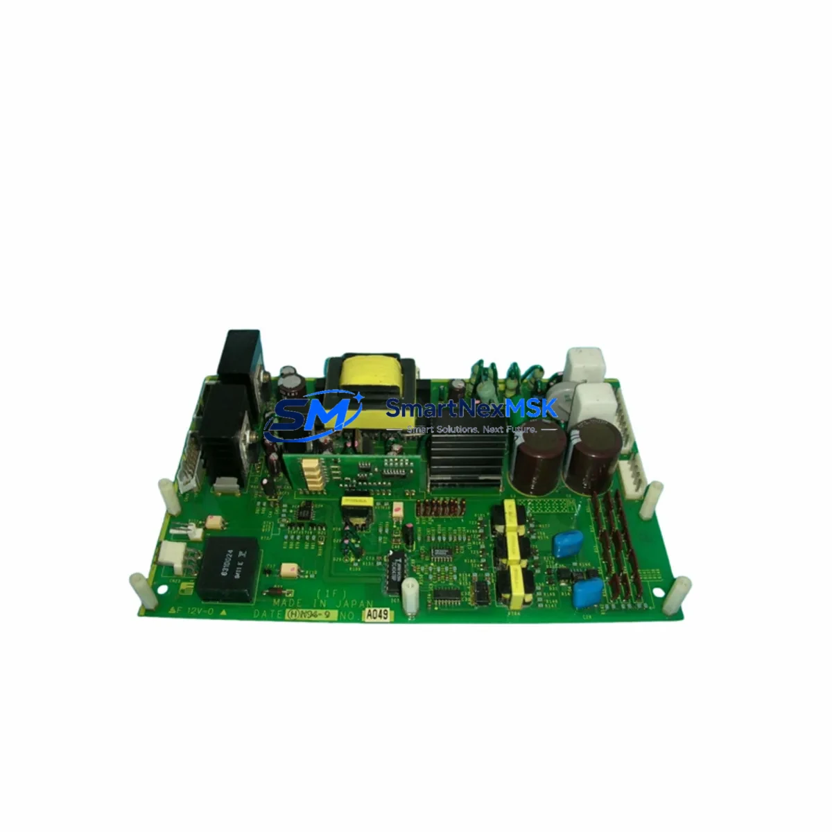
| Part Number / SKU | EP-3531D C1-Z1 |
| Brand | FUJI Electric |
| Compatible Series | FRENIC (FRENIC-Mini, FRENIC-Eco, FRENIC-Multi, FRENIC-MEGA) |
| Component Type | Inverter Control Board (PCB Assembly) |
| Origin | Japan |
| Voltage Range | Per FRENIC series drive specification (200V / 400V class) |
| Communication Interface | RS-485 / optional fieldbus per drive variant |
| Mounting | Internal board-level installation; drive must be de-energized before replacement |
| Application Environment | Industrial automation, HVAC, pump/fan control, conveyor, process lines |
| Compatibility Verification | Match drive nameplate model and firmware revision before installation |
| Pre-Shipment Testing | Electrical continuity, connector integrity, functional check |
| Warranty | 12 Months from date of shipment |
| Lead Time | In-stock units ship within 1–3 business days |
| Maintenance Recommendation | Replace at first sign of fault codes F-01, F-02, or persistent communication errors |
Maintenance Planning for Continuous Operation
When a FRENIC inverter control board such as the EP-3531D C1-Z1 is flagged for replacement, experienced maintenance engineers know that the board itself is rarely the only component that warrants attention. A thorough cabinet inspection during the same maintenance window significantly reduces the risk of repeat failures and unplanned downtime.
Begin by inspecting the FRENIC drive power supply board and the gate driver board — both are subject to the same thermal and electrical stress cycles as the control board. If the EP-3531D C1-Z1 has failed due to a surge event, the DC bus capacitor bank and input EMC filter should be evaluated for degradation. Capacitor ESR drift is a common root cause of control board instability in aging FRENIC drives.
Check the FRENIC keypad / operator panel (TP-E1U or equivalent) for display faults and communication errors, as a faulty HMI panel can mask or misreport control board status. Inspect all control terminal wiring at the X1–X5 digital input terminals and the AI1/AI2 analog input terminals for loose connections, corrosion, or insulation breakdown — these are frequent sources of intermittent faults that are incorrectly attributed to board failure.
For drives integrated into a PLC-controlled system, verify the integrity of the RS-485 communication cable and the fieldbus option card (such as the OPC-G1-PRT PROFIBUS card or OPC-G1-DEV DeviceNet card) if installed. A degraded communication link can cause the PLC to report inverter faults that are actually network-layer issues rather than drive hardware failures.
Also review the input fuse assembly and molded case circuit breaker (MCCB) upstream of the drive. Nuisance tripping or slow-blow fuse degradation can subject the control board to undervoltage stress over time. Downstream, inspect the output reactor or dV/dt filter if long motor cable runs are present, as reflected wave voltage can stress the drive output stage and indirectly affect control board longevity.
Finally, if your facility uses FUJI FRENIC-MEGA or FRENIC-Multi drives in a multi-drive cabinet, consider stocking the EP-3531D C1-Z1 alongside compatible control boards for adjacent drive models to consolidate your spare parts inventory and reduce per-unit procurement overhead.
Site Replacement Workflow
Replacing the EP-3531D C1-Z1 in the field follows a structured procedure to ensure system compatibility and minimize drive commissioning time:
1. Pre-Replacement Verification: Confirm the replacement board part number matches the installed unit exactly. Cross-reference the drive nameplate (model, voltage class, capacity) with the board revision label. If the existing board carries a firmware sticker or revision marking, note it before removal.
2. Safe Isolation: Isolate the drive from mains power and allow a minimum of 10 minutes for DC bus capacitors to discharge. Verify bus voltage with a calibrated meter before opening the drive enclosure. Follow your site LOTO (Lockout/Tagout) procedure.
3. Board Removal and Installation: Photograph all connector positions before disconnecting. Remove the control board by releasing the retaining screws and carefully disconnecting the ribbon cables and terminal connectors. Install the EP-3531D C1-Z1 replacement in reverse order, ensuring all connectors are fully seated.
4. Parameter Restoration: Restore drive parameters from a saved backup using the FRENIC keypad or FUJI Loader PC software. If no backup exists, re-enter critical parameters including motor nameplate data, acceleration/deceleration ramps, and PID settings before energizing.
5. Commissioning Test: Energize the drive in local control mode and verify no fault codes are present. Run the motor at low speed (5–10 Hz) and confirm output current, frequency display, and analog feedback signals are within expected ranges before returning the drive to automatic/remote control.
This workflow supports rapid recovery from unplanned outages and is equally applicable to planned maintenance shutdowns, helping maintenance teams achieve consistent, repeatable results across multiple FRENIC drive installations.
Spare Parts Support FAQ
Q1: How do I confirm the EP-3531D C1-Z1 is compatible with my specific FRENIC drive model?
Cross-reference the drive model number on the nameplate with the board part number printed on the installed control board. The EP-3531D C1-Z1 is used across multiple FRENIC series variants; however, sub-variants (C1, Z1 suffixes) indicate specific hardware revisions. Contact our technical team with your drive model and serial number for confirmation before ordering if you are uncertain.
Q2: What is included in the 12-month warranty and what does it cover?
The 12-month warranty covers manufacturing defects and component failures under normal operating conditions from the date of shipment. It does not cover damage resulting from incorrect installation, overvoltage events, physical impact, or operation outside the drive’s rated parameters. Warranty claims are processed with return shipment and replacement dispatch within 5 business days of fault confirmation.
Q3: Can this board be used to replace an older or discontinued FRENIC control board revision?
In many cases, yes — FUJI Electric maintains a degree of backward compatibility across FRENIC control board revisions. However, firmware and hardware revision mismatches can cause parameter incompatibility or fault code differences. We recommend verifying the revision suffix (C1-Z1) against your installed board and consulting the FRENIC service manual for your drive model. Our team can assist with cross-reference verification.
Q4: What is your typical lead time and how are units tested before shipment?
In-stock units are dispatched within 1–3 business days. Each EP-3531D C1-Z1 board undergoes pre-shipment inspection covering electrical continuity, connector integrity, and visual inspection for component damage. Units are packed in anti-static packaging with protective foam inserts to prevent transit damage. Expedited shipping options are available for emergency downtime recovery situations.
© 2026 SMARTNEXMSK. All rights reserved.
Original Source: https://smartnexmsk.com
Contact: sales@smartnexmsk.com | +86 18259474341