FUJI NB3-P34-AC Retrofit-Ready PID Controller for PXR Series Control Systems
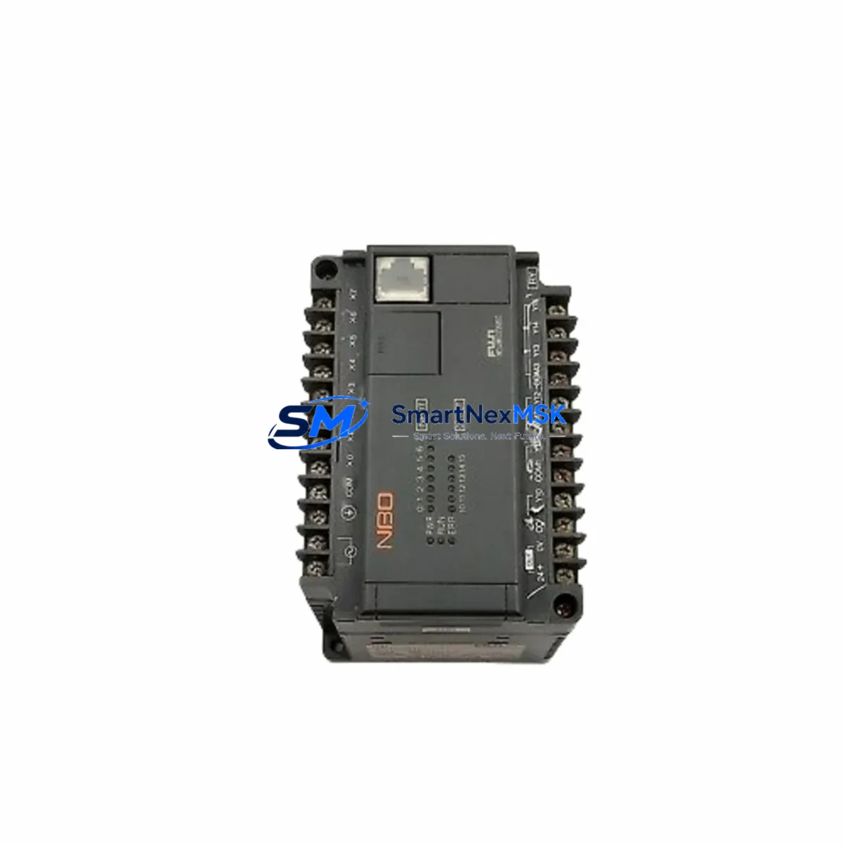
The FUJI NB3-P34-AC is a 1/16 DIN PID process controller engineered for seamless compatibility with FUJI Electric’s PXR Series control architecture. Designed to serve as a direct retrofit replacement for discontinued or end-of-life PXR-series units, the NB3-P34-AC supports AC power input with relay output, making it a reliable drop-in solution for legacy temperature and process control panels across manufacturing, chemical processing, food production, and industrial HVAC applications.
Whether you are managing a planned system upgrade or responding to an unplanned failure of an existing PXR controller, the NB3-P34-AC delivers the parameter compatibility, wiring footprint, and communication behavior required to restore full process control with minimal engineering rework. SMARTNEXMSK maintains verified in-stock inventory of this unit and ships with a 12-month warranty covering manufacturing defects and functional performance.
Upgrade Compatibility Table
| Parameter | NB3-P34-AC Specification | Retrofit Notes |
|---|---|---|
| Power Supply | AC 100–240 V, 50/60 Hz | Verify panel supply voltage before installation; compatible with standard industrial AC rails |
| Form Factor | 1/16 DIN (48 × 48 mm panel cutout) | Direct panel cutout match for most PXR-series predecessors; no panel modification required |
| Output Type | Relay output (SPDT) | Confirm existing wiring uses relay-type output; SSR-output variants require separate SKU |
| Input Compatibility | Thermocouple (K, J, T, E, R, S, B) / RTD (Pt100) | Verify sensor type and wiring polarity before commissioning |
| Communication | RS-485 (FUJI MODBUS-compatible, optional) | Confirm SCADA/HMI polling address and baud rate settings match existing network configuration |
| Mounting | Panel-mount, front bezel clip | Retain original mounting clips where possible; replacement clip kits available |
| Replacement Target | PXR3, PXR4, PXR5, NB3 legacy variants | Parameter migration via front keypad or FUJI PXR configuration software |
| Warranty | 12 Months | Covers manufacturing defects and functional performance from date of shipment |
Retrofit Planning for Existing Automation Systems
A successful retrofit of the FUJI NB3-P34-AC into an existing control system requires careful pre-installation planning across several interdependent subsystems. Before removing the legacy controller, engineers should document all current PID parameters — proportional band, integral time, derivative time, setpoint values, and alarm thresholds — either manually from the front display or by exporting configuration data via the RS-485 communication port if the existing unit supports it.
Terminal wiring is a critical checkpoint. The NB3-P34-AC uses a standard rear-terminal block layout consistent with the PXR Series, but technicians should cross-reference the terminal assignment diagram against the existing panel wiring schedule. Pay particular attention to the sensor input terminals (terminals 7–9 for thermocouple, terminals 7–10 for RTD Pt100), the relay output terminals (terminals 1–3), and the AC power supply terminals (terminals 11–12). Incorrect wiring of the sensor input polarity is the most common commissioning error in PXR-series retrofits.
For systems where the NB3-P34-AC is integrated into a larger FUJI Electric control platform — for example, a panel also containing a FUJI FALDIC-W series servo drive, a FUJI FRENIC-Mini inverter, or a FUJI Alpha 5 Smart servo amplifier — the communication network topology must be reviewed. If the existing RS-485 MODBUS network includes multiple nodes such as a FUJI PXR5 master controller or a FUJI ZEN programmable relay, the replacement unit’s station address must be configured to match the original node address before the network is re-energized.
HMI screen mapping is another area requiring attention. If the process control panel uses a FUJI UG series HMI or a third-party touch panel communicating with the PXR controller via MODBUS RTU, the register map for setpoint, process value, and alarm status must be verified against the NB3-P34-AC register table. In most PXR-to-NB3 migrations, the core holding registers are preserved, but alarm output register addresses may differ by one offset depending on firmware revision.
Power budget verification is essential when the NB3-P34-AC is installed in a control cabinet alongside other active components. Confirm that the panel’s FUJI BW series molded-case circuit breaker or equivalent protective device is rated to handle the combined inrush current of all installed modules. For cabinets using a FUJI G series power supply module or a third-party 24 VDC auxiliary supply for transmitter loops, verify that the NB3-P34-AC’s AC input does not share a circuit with sensitive analog signal conditioning equipment without appropriate isolation.
Where the retrofit involves I/O expansion — for example, adding additional temperature zones to an existing PXR-based multi-loop system — consider whether supplementary FUJI PXR4 or PXR5 slave controllers are required alongside the NB3-P34-AC master unit. Multi-loop configurations using a shared RS-485 bus benefit from consistent firmware versions across all nodes to avoid polling timeout issues during system startup.
Downtime Control During System Migration
Minimizing production downtime during a PXR-series controller replacement requires a structured migration sequence. Begin by scheduling the physical swap during a planned maintenance window, ideally when the process is already at a cold or idle state. Before powering down the existing system, capture a full screenshot or written record of all displayed parameters on the legacy controller’s front panel — setpoint, PID constants, alarm 1 and alarm 2 setpoints, and any active communication settings.
Once the NB3-P34-AC is physically installed and wired, perform a cold power-up with the process sensor disconnected. Confirm that the unit powers on correctly, displays the expected input type, and responds to front-panel keypad navigation before connecting the live sensor. This step isolates any wiring errors before they can affect the process or trigger nuisance alarms downstream.
Re-enter all documented PID parameters manually via the front keypad, or transfer them via the RS-485 configuration interface if a FUJI PXR configuration cable and software are available. After parameter entry, reconnect the sensor and allow the controller to stabilize at the process setpoint in manual mode before switching to automatic PID control. Monitor the first 15–30 minutes of automatic operation closely to confirm that the control response matches the pre-retrofit behavior. If oscillation or offset is observed, a brief auto-tune cycle using the NB3-P34-AC’s built-in AT function will recalibrate the PID constants to the actual process dynamics.
For systems where continuous process control is critical and a cold shutdown is not feasible, a parallel installation approach — where the NB3-P34-AC is pre-configured and verified on a bench test rig before the live swap — reduces the in-panel commissioning time to under 30 minutes in most cases. SMARTNEXMSK provides pre-shipment functional testing on all NB3-P34-AC units, confirming power-up, input response, relay output switching, and communication handshake before dispatch.
Retrofit Support FAQ
Q1: Is the FUJI NB3-P34-AC a direct drop-in replacement for the PXR3 and PXR4?
A: Yes, in the majority of installations. The NB3-P34-AC shares the same 1/16 DIN panel cutout (48 × 48 mm), the same rear terminal block layout, and compatible PID parameter structure with the PXR3 and PXR4. Minor differences in alarm register addresses may require HMI screen adjustments if the panel uses MODBUS communication. Always verify terminal assignments against the NB3-P34-AC wiring diagram before energizing.
Q2: What wiring changes are required when replacing a relay-output PXR unit with the NB3-P34-AC?
A: For relay-output-to-relay-output replacements, the existing wiring can typically be transferred terminal-for-terminal. Confirm that the load connected to the relay output (heater contactor, solenoid valve, or alarm device) does not exceed the NB3-P34-AC relay rating (3 A at 250 VAC resistive). If the original unit used an SSR (solid-state relay) voltage pulse output, the NB3-P34-AC relay output is not a direct substitute — contact SMARTNEXMSK to identify the correct SSR-output variant.
Q3: Can the NB3-P34-AC communicate with existing SCADA systems via MODBUS RTU?
A: Yes, provided the optional RS-485 communication module is fitted. The NB3-P34-AC supports FUJI MODBUS-compatible RTU protocol over RS-485 at configurable baud rates (2400–19200 bps). Station address, baud rate, and data format must be configured to match the existing SCADA polling parameters. SMARTNEXMSK can confirm register map compatibility with your specific SCADA or HMI system upon request.
Q4: What does the 12-month warranty cover, and what is the process for warranty claims?
A: The 12-month warranty covers manufacturing defects, component failures, and functional non-conformance under normal operating conditions from the date of shipment. It does not cover damage resulting from incorrect wiring, overvoltage, physical impact, or operation outside specified environmental limits. To initiate a warranty claim, contact SMARTNEXMSK at sales@smartnexmsk.com with your order reference, a description of the fault, and photographic evidence of the installation. Replacement or repair will be arranged within 5 business days of claim verification.
© 2026 SMARTNEXMSK. All rights reserved.
Original Source: https://smartnexmsk.com
Contact: sales@smartnexmsk.com | +86 18259474341