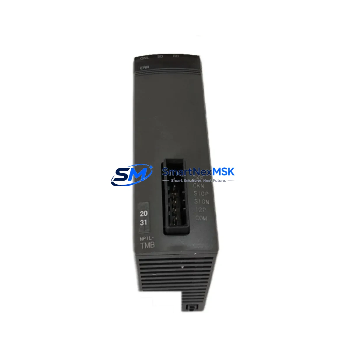
FUJI NP1L-RJ1 Retrofit-Ready RJ Interface Module for NP1L Series Control Systems
The FUJI NP1L-RJ1 is a dedicated RJ-interface communication module engineered for the FUJI NP1L Series programmable logic controller platform. As legacy NP1L-series control systems approach end-of-life and original spare parts become increasingly scarce, the NP1L-RJ1 remains one of the most sought-after retrofit components for engineers tasked with sustaining, modernizing, or migrating aging automation infrastructure. Whether you are replacing a failed communication link in a running production line, upgrading a control cabinet to support modern SCADA connectivity, or executing a phased migration away from discontinued hardware, the NP1L-RJ1 provides a verified, wiring-compatible solution that minimizes engineering rework and unplanned downtime.
Our inventory is sourced from authorized distribution channels and subject to full functional testing prior to shipment. Every unit is covered by a 12-month warranty against manufacturing defects and communication faults, giving procurement and maintenance teams the confidence to plan long-cycle retrofit projects without the risk of sourcing untested surplus stock.
Upgrade Compatibility Table
| Parameter | Detail |
|---|---|
| Compatible Platform | FUJI NP1L Series PLC |
| Module Type | RJ Interface Communication Module |
| Interface Standard | RJ (RS-232C / RS-485 compatible per NP1L backplane spec) |
| Backplane Slot | NP1L-series expansion rack / base unit slot |
| Installation Method | Direct slot insertion — no adapter required for NP1L base units |
| Wiring Compatibility | Terminal-compatible with original NP1L-RJ1 wiring harness |
| Communication Compatibility | FUJI proprietary loader protocol; supports NP1L CPU link and HMI connection |
| Replacement Recommendation | Direct drop-in for failed or end-of-life NP1L-RJ1 units |
| Commissioning Notes | Verify module address DIP switch settings match original configuration before power-on |
| Warranty | 12 Months — covers communication faults and manufacturing defects |
Retrofit Planning for Existing Automation Systems
Successful integration of the NP1L-RJ1 into an existing control system requires a structured pre-installation review. Engineers should begin by auditing the NP1L CPU module — typically an NP1L-CPU1 or NP1L-CPU2 variant — to confirm firmware revision compatibility with the communication module. The CPU’s program memory should be backed up to a programming cable or laptop running FUJI’s SX-Programmer before any hardware is disturbed.
Next, inspect the NP1L base unit and expansion rack for available communication slots. In multi-rack configurations, the NP1L-RS1 remote I/O expansion module and any installed NP1L-DI16 or NP1L-DO16 digital I/O modules must remain undisturbed during the RJ interface swap to avoid triggering I/O address conflicts. Confirm that the NP1L power supply module — commonly the NP1L-PS1 — provides sufficient current budget for the additional communication module load; the NP1L-RJ1 draws a modest 5 VDC supply from the backplane, but total rack current must remain within the power supply’s rated output.
For systems where the NP1L-RJ1 is used to connect a FUJI UG Series HMI (such as the UG221H or UG430H), verify that the HMI communication parameters — baud rate, station number, and protocol selection — match the settings stored in the replacement module’s DIP switches. Mismatched station addresses are the most common cause of communication failure after a module swap and can be resolved in under five minutes with a programming cable connected to the CPU’s loader port.
In applications where the NP1L-RJ1 bridges the PLC to a FUJI FRENIC series inverter or third-party variable frequency drive via RS-485, the communication cable shielding and termination resistor configuration should be re-verified after module replacement. The original cable can typically be reused without modification, provided the connector pinout is confirmed against the NP1L-RJ1 terminal diagram.
For sites migrating from the NP1L platform toward a newer FUJI NP8 Series or MICREX-SX Series controller, the NP1L-RJ1 can serve as a transitional communication bridge during parallel-run commissioning, allowing the legacy and new control systems to share HMI and SCADA data links while the migration program is validated. This approach significantly reduces the risk of production interruption during the cutover phase.
Downtime Control During System Migration
Minimizing unplanned downtime is the primary engineering objective in any NP1L-RJ1 replacement or system migration project. The recommended approach is a hot-standby swap procedure: with the control system in a safe, de-energized state, remove the failed or end-of-life NP1L-RJ1 from its backplane slot, insert the replacement unit, and restore power. Because the NP1L CPU retains its program in battery-backed RAM — assuming the NP1L lithium backup battery is serviceable — no program reload is required in most cases.
Before returning the system to automatic mode, perform a communication link check from the HMI or SCADA workstation to confirm that all data tags are resolving correctly. For systems with multiple communication paths — for example, a simultaneous RS-232C loader connection and an RS-485 inverter link — test each channel independently. Document the pre-swap and post-swap communication diagnostics for maintenance records.
Where a full system migration is planned rather than a like-for-like replacement, schedule the cutover during a planned maintenance window and prepare a rollback procedure that preserves the original NP1L-RJ1 and its wiring harness until the new system has completed a full production cycle without fault. This staged approach protects against unforeseen compatibility issues and ensures that field control continuity is maintained throughout the transition.
Retrofit Support FAQ
Q1: Is the NP1L-RJ1 a direct replacement for the original FUJI NP1L-RJ1 without any wiring changes?
Yes. The NP1L-RJ1 is a direct slot-compatible replacement for the original module. Terminal wiring, backplane connector, and DIP switch layout are identical to the factory specification. No adapter plates or wiring modifications are required for standard NP1L base unit installations.
Q2: What commissioning steps are required after installing the replacement NP1L-RJ1?
After installation, verify that the module address DIP switches match the original configuration (photograph the original before removal). Power on the rack and confirm the module’s status LED indicates normal operation. From the HMI or programming software, initiate a communication test to each connected device. Full commissioning typically takes 15–30 minutes for a single-rack system.
Q3: Can the NP1L-RJ1 be used during a migration from the NP1L platform to a newer FUJI controller?
Yes. The NP1L-RJ1 can operate in parallel-run mode during a phased migration, maintaining existing HMI and SCADA communication links while the new controller platform is commissioned alongside the legacy system. This approach is recommended for critical production environments where a hard cutover is not feasible.
Q4: What does the 12-month warranty cover, and what is the process for a warranty claim?
The 12-month warranty covers communication faults, backplane interface failures, and manufacturing defects under normal operating conditions. Units that fail within the warranty period are replaced or refunded. To initiate a claim, contact our sales team with the order reference and a description of the fault. Pre-shipment functional testing documentation is available upon request.
© 2026 SMARTNEXMSK. All rights reserved.
Original Source: https://smartnexmsk.com
Contact: sales@smartnexmsk.com | +86 18259474341