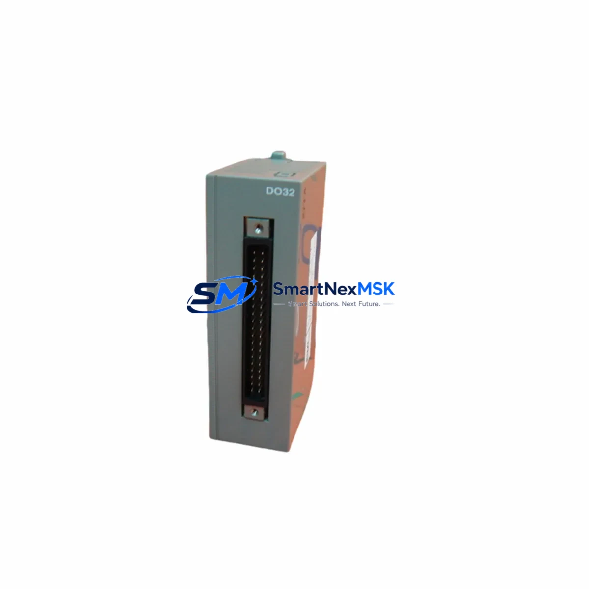
FUJI NV1Y32T05P1 Retrofit-Ready Digital Output for NV Series Control Systems
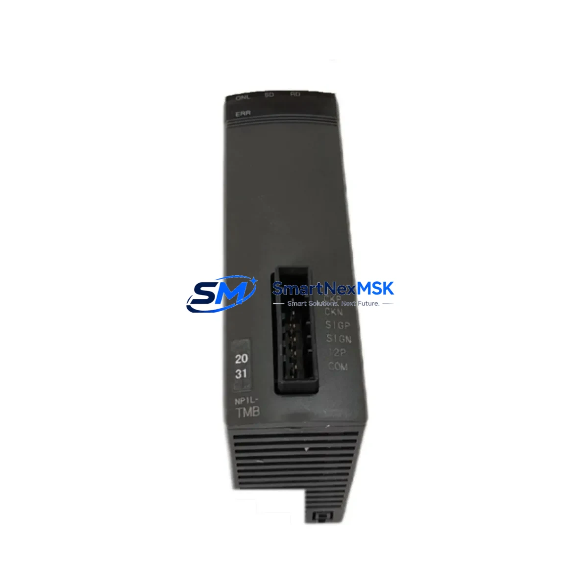
The FUJI NV1Y32T05P1 is a 32-point transistor output module engineered for the FUJI NV Series programmable logic controller platform. As legacy NV Series installations approach end-of-life or require capacity expansion, the NV1Y32T05P1 serves as the primary retrofit and replacement solution — offering full backplane compatibility, identical terminal pitch, and transparent program-level integration with existing NV Series CPU modules such as the NV1L14DT11 and NV1L20DT11.
For engineers managing aging control cabinets, the NV1Y32T05P1 eliminates the need for full system replacement. Whether you are restoring a discontinued spare, expanding I/O capacity on an existing rack, or migrating from an earlier NV output module variant, this module slots directly into the NV Series base unit without requiring changes to the ladder logic program or HMI screen mapping. Output addressing is preserved, and no re-download of the CPU program is required in most standard retrofit scenarios.
Upgrade Compatibility Table
| Parameter | NV1Y32T05P1 (This Module) | Retrofit Notes |
|---|---|---|
| Output Points | 32 points (transistor, NPN sink) | Matches legacy 32-pt output modules in NV Series racks |
| Rated Output Voltage | 5–24 VDC | Verify field device supply voltage before wiring |
| Output Current per Point | 0.5 A | Check load current against existing terminal wiring |
| Backplane Interface | NV Series expansion bus connector | Direct plug-in; no adapter required |
| Installation Slot | Any I/O slot on NV Series base unit | Confirm slot address assignment in CPU configuration |
| Communication Compatibility | NV Series internal bus | No protocol migration required |
| Terminal Block | 40-pin removable terminal | Reuse existing field wiring harness where pitch matches |
| Replacement Recommendation | Direct drop-in for NV Series output slots | Verify module address in CPU I/O map after installation |
| Commissioning Focus | Output force test, address verification | Use FUJI programming tool (FP-WIN or equivalent) for I/O check |
| Warranty | 12 Months | Covered from date of shipment; includes DOA replacement |
Retrofit Planning for Existing Automation Systems
Successful integration of the NV1Y32T05P1 into an existing control system begins with a thorough pre-installation audit. Before removing the failed or obsolete output module, engineers should document the current I/O address map from the NV Series CPU — typically the NV1L14DT11 or NV1L20DT11 — and confirm that the replacement module will occupy the same logical slot address. Mismatched slot assignments are the most common cause of post-retrofit output errors and can result in unintended actuator activation during the first power-on sequence.
Terminal wiring is the next critical checkpoint. The NV1Y32T05P1 uses a 40-pin removable terminal block, and in most NV Series installations the existing field wiring harness can be transferred directly. However, engineers should verify the terminal pitch and confirm that the load current per output point does not exceed 0.5 A. For high-current loads previously managed by relay output modules, an interposing relay or solid-state relay buffer may be required between the NV1Y32T05P1 transistor outputs and the field devices.
Power supply capacity is another area that requires attention during retrofit planning. The NV Series base unit draws module power from the NV1PA power supply module mounted on the left side of the rack. When adding or replacing output modules, confirm that the total current draw across all installed modules — including the NV1Y32T05P1, any NV1X input modules, and communication modules such as the NV1L-RS4 serial link unit — does not exceed the rated output of the installed power supply. If the existing NV1PA is operating near capacity, a supplementary power supply or rack expansion may be necessary before the retrofit proceeds.
For systems that include an NV Series HMI panel — such as a FUJI UG series operator terminal — engineers should verify that all output coil addresses referenced in HMI screen objects remain valid after the module swap. In most cases, because the NV1Y32T05P1 preserves the same I/O address structure as its predecessor, HMI screen data does not require modification. However, a full screen-by-screen functional test is recommended before returning the line to production, particularly for output-driven alarm indicators and motor run status displays.
Where the retrofit involves migrating from an older NV Series rack to a new base unit, engineers should also account for the NV Series expansion cable and any NV1EX expansion base units in the system. The NV1Y32T05P1 is compatible across all standard NV Series base configurations, and its installation in an expansion rack follows the same slot-address assignment rules as the main rack. Programming cable connection — typically via the NV Series mini-USB or RS-232 port on the CPU — should be established before powering the new module to allow immediate I/O verification using the online monitoring function.
Downtime Control During System Migration
Minimizing production downtime during an NV Series output module replacement requires a structured hot-swap preparation protocol. Before the maintenance window opens, engineers should use the FUJI programming software to export the current CPU program and I/O configuration as a backup file. This backup serves as the recovery baseline if any unexpected behavior occurs after the NV1Y32T05P1 is installed.
During the physical swap, all output loads connected to the module being replaced should be de-energized and locked out in accordance with local LOTO procedures. The NV1Y32T05P1’s removable terminal block allows the field wiring harness to be pre-wired and tested on the bench before the maintenance window, reducing in-cabinet work time to the minimum required for module insertion and terminal block reconnection.
After power restoration, the recommended commissioning sequence is: (1) confirm CPU status LED is normal, (2) enter online monitoring mode and verify that all 32 output points of the NV1Y32T05P1 appear in the I/O map at the expected addresses, (3) perform a forced output test on each point to confirm field device response, and (4) release the system to automatic mode under operator supervision for the first production cycle. This sequence typically completes within 15–30 minutes for a single-module retrofit, keeping unplanned downtime to an absolute minimum.
For systems where continuous operation is critical, a parallel rack strategy — pre-configuring a spare NV Series base unit with the NV1Y32T05P1 and all associated modules including the NV1PA power supply and NV1X input modules — allows the entire rack to be swapped as a unit during a scheduled micro-shutdown, with the original rack retained as a tested fallback.
Retrofit Support FAQ
Q: Is the NV1Y32T05P1 a direct replacement for all 32-point output modules in the NV Series?
A: The NV1Y32T05P1 is a direct drop-in replacement for NV Series transistor output modules with the same 32-point, NPN sink configuration. If your existing module is a relay output type or a different point count, please confirm the output type and terminal configuration before ordering. Our technical team can assist with cross-reference verification.
Q: Do I need to modify my CPU program after installing the NV1Y32T05P1?
A: In standard retrofit scenarios where the module occupies the same slot address as the replaced unit, no program modification is required. The NV Series CPU automatically maps I/O addresses by slot position. A program re-download is only necessary if the slot address changes or if the CPU configuration file is updated.
Q: What wiring checks should I perform before powering up the new module?
A: Verify that all field device loads are within the 0.5 A per point rating, confirm the common terminal wiring matches the NPN sink configuration, and check that the 24 VDC field power supply is correctly connected to the module’s external power terminals. Insulation resistance testing between output terminals and chassis ground is recommended for installations in high-humidity or industrial environments.
Q: What does the 12-month warranty cover?
A: All NV1Y32T05P1 units ship with a 12-month warranty from the date of shipment. The warranty covers manufacturing defects and DOA (dead-on-arrival) units. Each module undergoes pre-shipment functional testing. Warranty claims are processed with priority turnaround, and replacement units are dispatched from stock to minimize your system downtime.
© 2026 SMARTNEXMSK. All rights reserved.
Original Source: https://smartnexmsk.com
Contact: sales@smartnexmsk.com | +86 18259474341