FUJI NW0E32R-3 Maintenance-Ready Spare for C Series Automation
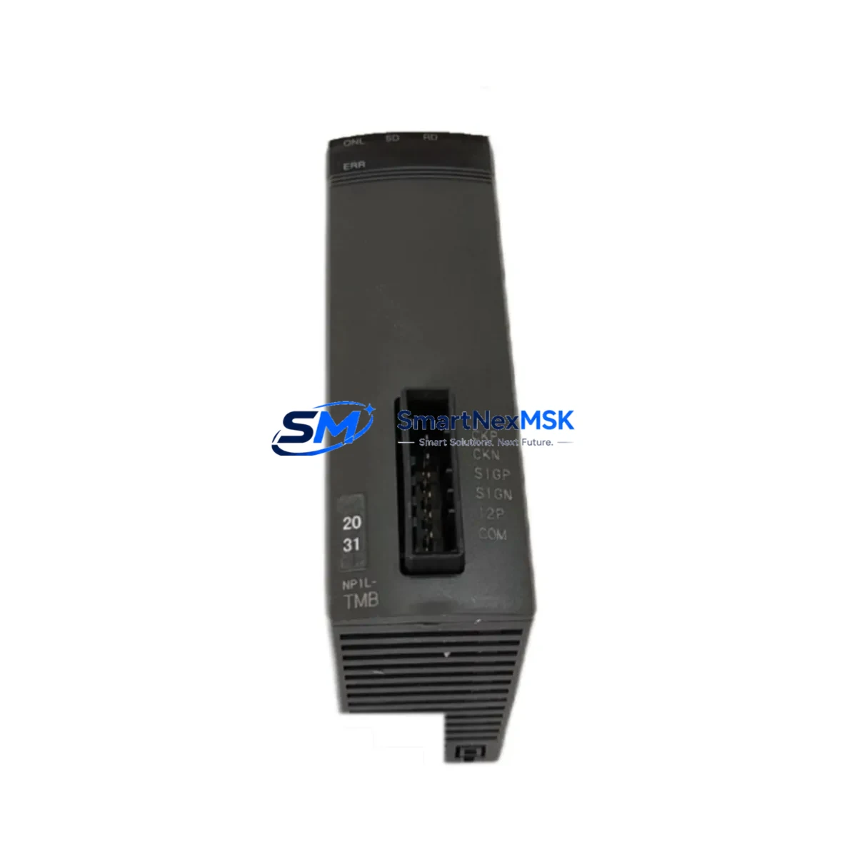
The FUJI NW0E32R-3 (also referenced as NWOE32R-3) is an original 32-point relay output expansion module designed for FUJI Electric’s C Series programmable logic controller platform. For maintenance engineers managing aging control systems, this module represents a critical spare that directly impacts production uptime. Whether you are executing a planned shutdown inspection, responding to an unscheduled relay failure, or building a strategic spare parts inventory for a multi-line facility, the NW0E32R-3 delivers verified compatibility, tested output performance, and a 12-month warranty backed by documented pre-shipment inspection.
Industrial facilities running FUJI C Series PLCs frequently encounter relay output degradation after years of continuous switching cycles — particularly in high-frequency actuator control, motor starter interlock, and solenoid valve command circuits. A failed output point on the NW0E32R-3 can cascade into line stoppages that cost far more than the module itself. Stocking this spare in your control room cabinet or MRO warehouse is a proven strategy for reducing mean time to repair (MTTR) and maintaining SLA compliance with production targets.
Spare Maintenance Table
| Parameter | Specification |
|---|---|
| SKU / Part Number | NW0E32R-3 (NWOE32R-3) |
| Brand | FUJI Electric |
| Series | C Series PLC |
| Module Type | Digital Output — Relay |
| Output Points | 32-point relay output |
| Output Type | Relay contact (NO) |
| Rated Load Voltage | AC 250V / DC 30V |
| Max Load Current | 2A per point |
| Isolation Method | Relay mechanical isolation |
| Compatibility | FUJI C Series PLC CPU units and expansion racks |
| Origin | Japan (Original FUJI Electric) |
| Installation | DIN rail / expansion rack slot mount |
| Operating Temperature | 0°C to 55°C |
| Storage Temperature | -20°C to 70°C |
| Humidity | 5% to 95% RH (non-condensing) |
| Application Environment | Industrial automation, process control, machine tool, utilities |
| Pre-Shipment Testing | Yes — functional output verification |
| Warranty | 12 months from date of shipment |
| Condition | Original / New surplus |
Maintenance Planning for Continuous Operation
When a maintenance or procurement engineer schedules replacement of the NW0E32R-3, the replacement event should be treated as a broader control cabinet inspection opportunity. Relay output modules do not fail in isolation — their degradation is often symptomatic of upstream power quality issues, wiring fatigue, or excessive load cycling that affects adjacent components in the same I/O rack.
During the same maintenance window, engineers should inspect and consider stocking the following associated components:
- FUJI C Series CPU module (e.g., NW0P14R-31 or equivalent) — verify firmware version compatibility and battery backup status before swapping the output module.
- 24VDC power supply module for the C Series rack — relay output modules draw switching current from the internal bus; a degraded PSU can cause intermittent relay chatter or false outputs.
- NW0E32T-3 transistor output module — in mixed I/O configurations, the transistor output counterpart is often installed alongside the NW0E32R-3 for high-speed digital outputs; inspect both during planned maintenance.
- Input expansion module (e.g., NW0E32S-3 or NW0E16S-3) — digital input modules in the same rack should be checked for contact bounce or signal noise that may be misinterpreted as relay command errors.
- Terminal blocks and wiring harnesses — relay output modules connect to field devices via screw-terminal or push-in terminal blocks; inspect for loose connections, oxidation, and insulation fatigue, especially on high-cycle output points.
- Fuse holders and miniature circuit breakers on the output load side — relay contacts driving inductive loads (motors, solenoids) are subject to arc erosion; verify protective fusing is within rated values.
- Communication module (e.g., FUJI C Series Ethernet or RS-485 link module) — if the PLC communicates with a SCADA or HMI system, confirm the communication module is functioning correctly after any rack disturbance.
- FUJI GOT / HMI panel connected to the C Series CPU — after module replacement, verify that HMI tag mappings and alarm setpoints remain intact and that no communication timeout errors are logged.
- Signal isolators on analog I/O channels in the same cabinet — while the NW0E32R-3 is a digital relay module, co-located analog signal isolators should be checked for ground loop issues that can be introduced during wiring work.
- Expansion rack backplane — if the NW0E32R-3 is installed in an expansion rack rather than the main CPU rack, inspect the backplane connector and bus terminator for physical damage or corrosion.
This holistic inspection approach reduces the probability of a secondary failure within weeks of the initial repair, which is a common cause of repeat unplanned downtime in aging C Series installations.
Site Replacement Workflow
Replacing the FUJI NW0E32R-3 on-site is a straightforward procedure when the correct spare is pre-staged and the replacement workflow is documented in advance. The following steps outline a best-practice approach for minimizing downtime during module swap:
- Pre-replacement verification: Confirm the replacement module SKU matches NW0E32R-3 exactly. Cross-reference the label on the module body with the purchase documentation. Verify the C Series rack slot assignment in the PLC configuration software before powering down.
- Safe power-down sequence: Follow the facility’s lockout/tagout (LOTO) procedure. De-energize the output load circuits before removing the module to prevent arc flash on relay contacts.
- Module extraction and inspection: Remove the faulty module and inspect the rack slot connector for bent pins or debris. Clean with dry compressed air if necessary.
- Spare installation: Insert the NW0E32R-3 replacement module firmly into the rack slot. Reconnect field wiring terminal blocks, verifying wire assignments against the as-built wiring diagram.
- Power-up and functional test: Restore power in sequence — rack power supply first, then CPU. Force-test each output point from the PLC programming terminal or HMI to confirm relay actuation on all 32 points before returning the system to automatic mode.
- Documentation update: Record the replacement date, module serial number, and test results in the equipment maintenance log. Update the spare parts inventory to trigger reorder of a replacement spare.
This workflow is compatible with both hot-standby and single-CPU C Series configurations. For systems with redundant CPU modules, consult the FUJI C Series redundancy manual before initiating any rack maintenance to avoid unintended failover events.
Spare Parts Support FAQ
Q1: What is the shelf life and storage recommendation for the NW0E32R-3 spare module?
The NW0E32R-3 can be stored for 3–5 years under proper conditions (temperature 15–25°C, humidity below 60% RH, away from direct sunlight and corrosive atmospheres). Store in the original anti-static packaging inside a sealed cabinet. Perform a functional bench test before deploying a long-stored spare to confirm relay contact integrity.
Q2: How do I verify compatibility with my existing FUJI C Series PLC configuration?
The NW0E32R-3 is designed for the FUJI C Series expansion rack system. Compatibility is confirmed by matching the rack type (main or expansion), slot capacity, and I/O assignment in the PLC configuration software. If your system uses an older C Series CPU variant, contact our technical team with your CPU model number for a compatibility cross-reference before ordering.
Q3: What pre-shipment testing is performed on each NW0E32R-3 unit?
Each unit undergoes functional output verification prior to shipment: all 32 relay output points are tested for actuation, contact resistance is measured, and the module is inspected for physical damage. A test report is available upon request. Units are shipped in anti-static packaging with protective foam inserts to prevent transit damage.
Q4: What does the 12-month warranty cover, and what is the RMA process?
The 12-month warranty covers manufacturing defects and functional failures under normal operating conditions. It does not cover damage caused by incorrect installation, overvoltage, or physical mishandling. To initiate a warranty claim, contact our support team with the order number, failure description, and photos of the module. Replacement or repair will be arranged within 5 business days of claim approval.
© 2026 SMARTNEXMSK. All rights reserved.
Original Source: https://smartnexmsk.com
Contact: sales@smartnexmsk.com | +86 18259474341