GE 269PLUS-100P-120 Maintenance-Ready Spare for MULTILIN 269 Plus Automation
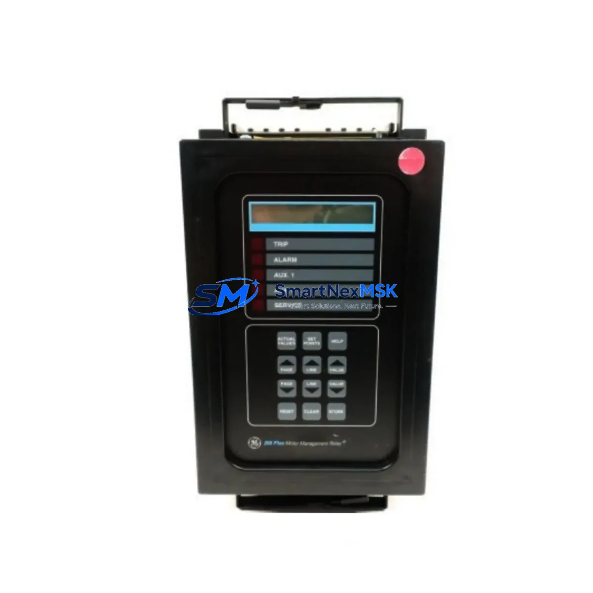
The GE MULTILIN 269PLUS-100P-120 is a full-featured motor management relay engineered for continuous-duty industrial environments where motor protection, fault isolation, and rapid restoration of operations are non-negotiable. As a maintenance-ready original spare, this unit is sourced, inspected, and dispatched to support planned maintenance cycles, emergency replacements, and long-term spare parts inventory strategies across manufacturing plants, water treatment facilities, oil & gas installations, and heavy process industries.
Motor protection relays are among the most critical components in any motor control center (MCC) or switchgear panel. When a 269PLUS-100P-120 fails or reaches end-of-life, the downstream impact is immediate: motor circuits lose overload, phase-loss, and thermal protection, exposing driven equipment to catastrophic damage. Maintenance engineers and procurement teams responsible for uptime continuity must treat this relay as a priority stocking item — particularly in aging MULTILIN 269 Plus installations where OEM support timelines are shortening.
This spare is fully compatible with the GE MULTILIN 269 Plus motor management platform and supports the standard 100–120 VAC control voltage range, making it a direct drop-in replacement without panel rewiring or firmware reconfiguration in most site configurations. Each unit undergoes functional verification and insulation testing prior to shipment, backed by a 12-month warranty covering manufacturing defects and operational failures under normal service conditions.
Spare Maintenance Table
| Parameter | Specification |
|---|---|
| Part Number / SKU | 269PLUS-100P-120 |
| Brand / Manufacturer | GE MULTILIN |
| Series | MULTILIN 269 Plus Motor Management Relay |
| Product Type | Motor Protection Relay |
| Control Voltage | 100–120 VAC, 50/60 Hz |
| Protection Functions | Overload, Phase Loss, Phase Unbalance, Ground Fault, Thermistor, Undercurrent, Jam/Stall |
| Communication | RS-485 Modbus RTU (standard) |
| Mounting | Panel / DIN rail compatible, standard MULTILIN 269 Plus footprint |
| Operating Temperature | -20°C to +60°C |
| Ingress Protection | IP40 (front panel) |
| Compatibility | Direct replacement for GE MULTILIN 269 Plus series installations |
| Origin | China (CN) |
| Pre-shipment Testing | Functional verification + insulation resistance test |
| Warranty | 12 Months from date of shipment |
| Typical Application | MCC panels, switchgear, pump/fan/compressor motor circuits |
Maintenance Planning for Continuous Operation
When scheduling a replacement of the 269PLUS-100P-120 in a motor control center, experienced maintenance engineers know that the relay itself is rarely the only component requiring attention. A thorough site inspection and planned replacement window should also address the following associated components to prevent repeat failures and maximize the value of each maintenance intervention:
The CT (current transformer) inputs feeding the 269 Plus relay should be verified for correct ratio and wiring polarity — mismatched CTs are a common source of nuisance trips after relay replacement. The control power supply module or transformer supplying the 100–120 VAC control voltage should be load-tested; a degraded supply can cause relay brownout or erratic protection behavior. RS-485 communication wiring and termination resistors should be inspected, as corroded terminals or missing terminations on the Modbus network will prevent SCADA integration from functioning correctly after the new relay is commissioned.
In the same cabinet, maintenance teams should inspect motor circuit breakers or MMS (motor management switches) for contact wear, and verify that contactor auxiliary contacts providing run/stop feedback to the relay are clean and making reliable contact. Terminal blocks and ferrule crimps on the relay’s I/O wiring should be retorqued to manufacturer specification — loose connections are a leading cause of intermittent relay faults in high-vibration environments.
For installations using the 269 Plus relay’s thermistor input for winding temperature monitoring, the PTC/NTC thermistor circuit continuity should be confirmed before commissioning the replacement unit. If the motor is equipped with a space heater contactor or anti-condensation heater circuit, verify that the heater control relay and its associated fuse are serviceable. Where the 269 Plus is integrated into a PLC or DCS system via Modbus, the communication parameters (baud rate, parity, device address) must be re-entered and verified against the site’s SCADA configuration after relay swap.
Procurement engineers building a comprehensive spare parts kit around the 269PLUS-100P-120 should also consider stocking surge protection devices (SPDs) for the control voltage input, auxiliary relays for trip circuit extension, and panel-mount fuse holders with appropriate fuse ratings for the relay’s control and output circuits. Maintaining a minimum of one cold-standby 269PLUS-100P-120 per critical motor circuit is the industry-standard recommendation for facilities operating under IEC 60300 or equivalent maintenance frameworks.
Site Replacement Workflow
Replacing a GE MULTILIN 269PLUS-100P-120 in the field follows a structured sequence to minimize downtime and ensure system compatibility is preserved:
1. Pre-isolation documentation: Before de-energizing the panel, photograph or record all relay settings — protection thresholds, time delays, CT ratios, communication parameters, and output relay assignments. The 269 Plus stores these in non-volatile memory, but the replacement unit will ship with factory defaults.
2. Safe isolation: Isolate the motor circuit at the upstream breaker and apply LOTO (lockout/tagout) per site safety procedures. Verify absence of voltage on the control supply terminals before disconnecting wiring.
3. Wiring transfer: Label all wiring before removal. The 269PLUS-100P-120 uses a standard terminal layout consistent across the 269 Plus series, allowing direct wire-for-wire transfer. Inspect each wire end for insulation damage or corrosion during transfer.
4. Parameter restoration: Re-enter all protection settings from the pre-isolation record. For sites with a SCADA-connected configuration backup, upload the saved parameter file via the RS-485 Modbus interface using GE’s EnerVista software or compatible third-party tools.
5. Commissioning verification: With the motor isolated, perform a secondary injection test or use the relay’s built-in test mode to verify trip output operation. Confirm Modbus communication is re-established with the PLC or DCS before returning the motor to service.
This workflow is applicable whether replacing a failed unit on an emergency basis or executing a scheduled life-cycle replacement as part of a planned maintenance program. The 269PLUS-100P-120’s compatibility with the existing 269 Plus wiring harness and panel cutout eliminates the need for panel modification, significantly reducing mean time to repair (MTTR) compared to cross-brand substitutions.
Spare Parts Support FAQ
Q1: Is the 269PLUS-100P-120 a direct replacement for older GE MULTILIN 269 Plus units already installed in my panel?
Yes. The 269PLUS-100P-120 is designed as a form-fit-function replacement for existing MULTILIN 269 Plus installations operating on 100–120 VAC control voltage. The terminal layout, mounting dimensions, and communication interface are consistent with the 269 Plus series, allowing direct substitution without panel modification. Always verify the control voltage rating on the nameplate of the unit being replaced before installation.
Q2: How is the unit tested before shipment, and what does the 12-month warranty cover?
Each 269PLUS-100P-120 spare undergoes functional verification testing — including protection function actuation, output relay operation, and communication interface check — as well as insulation resistance measurement prior to dispatch. The 12-month warranty covers manufacturing defects and operational failures arising under normal service conditions. It does not cover damage resulting from incorrect installation, overvoltage events, or unauthorized modification.
Q3: What is the recommended spare parts inventory strategy for critical motor circuits using the 269 Plus relay?
For motors classified as critical (single-point-of-failure for production continuity), the recommended strategy is to maintain one cold-standby 269PLUS-100P-120 on-site per relay installed. For non-critical motors in groups of five or more using the same relay model, a 1:5 ratio is generally acceptable. Spare units should be stored in their original packaging in a dry, temperature-controlled environment and inspected annually for storage condition compliance.
Q4: Can you supply the 269PLUS-100P-120 on a long-term or blanket order basis for multi-site maintenance programs?
Yes. Long-term supply arrangements, scheduled delivery programs, and multi-site procurement contracts are supported. Contact our sales team to discuss volume pricing, lead time commitments, and documentation packages (test reports, certificates of conformance) for your maintenance program requirements.
© 2026 SMARTNEXMSK. All rights reserved.
Original Source: https://smartnexmsk.com
Contact: sales@smartnexmsk.com | +86 18259474341