GE Multilin RE400REPJH1ABA Retrofit-Ready Relay for SR Series Control Systems
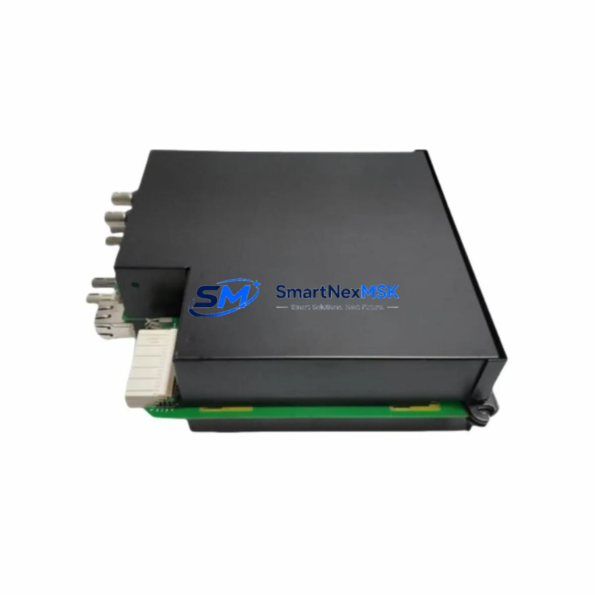
The GE Multilin RE400REPJH1ABA is a retrofit-ready protection relay engineered for seamless integration into existing SR Series control systems. Whether you are replacing an end-of-life unit, upgrading a legacy protection panel, or restoring a tripped protection circuit, this relay delivers full functional compatibility with the original SR Series architecture. It is a direct drop-in replacement for discontinued GE Multilin SR Series protection relays, enabling engineers to restore system protection without redesigning the control cabinet or rewriting PLC logic.
Industrial facilities running aging SR Series protection schemes face increasing pressure as original equipment reaches end-of-life and OEM spare parts become scarce. The RE400REPJH1ABA addresses this challenge directly: it maintains the same terminal block layout, communication interface, and protection function set as the original SR Series relay, minimizing retrofit engineering time and reducing the risk of commissioning errors. This relay is suitable for motor protection, feeder protection, and transformer protection applications across power distribution, oil and gas, water treatment, and heavy manufacturing environments.
Upgrade Compatibility Table
| Parameter | Details |
|---|---|
| SKU / Part Number | RE400REPJH1ABA |
| Brand | GE Multilin |
| Series | SR Series |
| Product Type | Protection Relay |
| Mounting / Form Factor | Panel-mount, compatible with standard SR Series cutout dimensions |
| Terminal Interface | Screw-terminal block; pin-compatible with original SR Series wiring harness |
| Communication Protocol | Modbus RTU / DNP3 (consistent with SR Series communication architecture) |
| Replacement Compatibility | Direct replacement for discontinued GE Multilin SR Series protection relays |
| Installation Requirement | Verify CT ratio, VT ratio, and protection setting parameters before energizing |
| Commissioning Focus | Confirm protection curve settings, trip thresholds, and communication node address |
| Warranty | 12 Months — covers manufacturing defects and functional failure under normal operating conditions |
| Origin | CN (Xiamen) |
Retrofit Planning for Existing Automation Systems
A successful retrofit of the RE400REPJH1ABA into an existing SR Series protection panel requires a structured pre-installation review. Before removing the original relay, engineers should document all existing protection settings, including overcurrent pickup values, time-dial settings, and instantaneous trip thresholds. These parameters must be re-entered into the replacement unit during commissioning to maintain the original protection coordination scheme.
The physical installation process begins with verifying that the control cabinet power supply — typically a 24 VDC or 125 VDC auxiliary supply — meets the relay’s input voltage specification. The terminal block wiring on the RE400REPJH1ABA follows the same numbering convention as the original SR Series relay, which significantly reduces rewiring effort. However, engineers should cross-reference the terminal diagram against the existing panel wiring schedule to confirm CT secondary connections, VT secondary connections, trip output contacts, and alarm output contacts are correctly mapped.
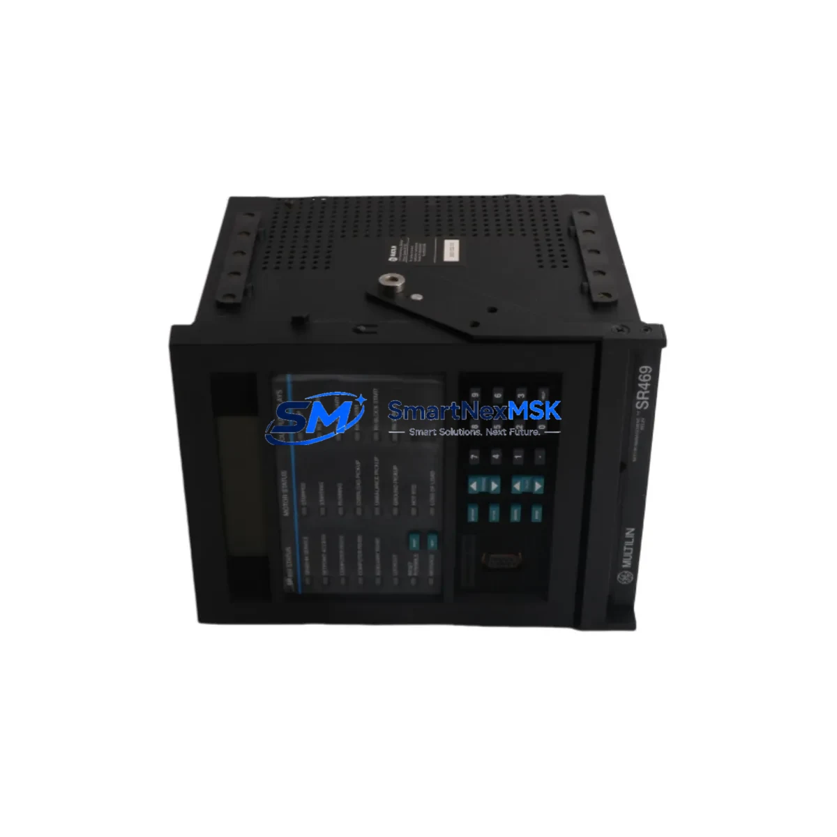
For facilities using a GE Multilin SR469 Motor Management Relay or SR750 Feeder Protection Relay in adjacent panels, the RE400REPJH1ABA integrates into the same protection coordination hierarchy without requiring changes to upstream relay settings. If the control system includes a GE D60 Line Distance Relay or GE T60 Transformer Management Relay as part of a broader protection scheme, the communication node address of the RE400REPJH1ABA must be configured to match the original relay’s Modbus or DNP3 address to avoid disrupting SCADA polling sequences.
In control cabinets where the SR Series relay interfaces with a GE Multilin 869 Motor Protection Relay or a GE Multilin 339 Motor Protection Relay, the I/O wiring for start/stop commands, status feedback, and fault annunciation should be verified against the original panel schematic. Where the existing system uses a GE RX3i PLC or GE PACSystems controller for supervisory control, the relay’s digital output contacts — used for trip, alarm, and ready signals — must be confirmed against the PLC input module’s voltage and current ratings before energizing the panel.
If the retrofit involves migrating from a hardwired protection scheme to a networked protection architecture, the RE400REPJH1ABA’s Modbus RTU port can be connected to an existing RS-485 communication bus shared with other SR Series devices. In systems where a GE Multilin EPM 9450 Power Meter or GE Multilin 1200 Series Current Transformer is already installed on the same bus, the communication wiring topology and termination resistor placement should be reviewed to ensure signal integrity across the full bus length.
For HMI integration, if the facility uses a GE iFIX SCADA or a third-party HMI platform with existing SR Series relay faceplates, the RE400REPJH1ABA’s register map should be compared against the original relay’s register map to confirm that all monitored data points — including current measurements, voltage measurements, power factor, and fault records — are available at the same Modbus register addresses. Where register address differences exist, HMI tag configurations will require updating before the system is returned to service.
Downtime Control During System Migration
Minimizing unplanned downtime during a protection relay retrofit requires a phased approach that preserves the original protection logic until the replacement unit is fully commissioned and verified. The recommended sequence begins with a complete backup of the original relay’s settings file using the GE EnerVista SR Series Setup software, if the original relay is still functional. This settings file serves as the baseline configuration for the RE400REPJH1ABA and eliminates the need to reconstruct protection parameters from engineering drawings alone.
Where the original relay has already failed and a settings backup is unavailable, protection parameters should be reconstructed from the most recent relay test records, protection coordination study, or as-built panel documentation. The RE400REPJH1ABA can be pre-configured on the bench using a laptop and the appropriate GE EnerVista configuration software before it is installed in the panel, reducing the time the protection circuit remains out of service.
During the physical swap, the control circuit should be isolated at the auxiliary supply breaker and the CT secondary circuits should be short-circuited at the relay terminal block before disconnecting the CT wiring. This prevents open-circuit CT conditions that could generate dangerous voltages during the relay exchange. Once the RE400REPJH1ABA is installed and wired, a secondary injection test using a relay test set should be performed to verify that the relay responds correctly to simulated fault currents before the CT short circuits are removed and the protection circuit is returned to service.
For facilities where continuous process protection is critical, a temporary protection scheme using a portable protection relay or a bypass contactor arrangement can maintain basic overcurrent protection during the relay exchange window, further reducing the operational risk of the retrofit. All commissioning activities should be documented in a relay test record that captures the as-found and as-left settings, test results, and the names of the engineers who performed and witnessed the commissioning tests.
Retrofit Support FAQ
Q1: Is the RE400REPJH1ABA a direct drop-in replacement for my existing SR Series relay?
The RE400REPJH1ABA is designed as a functional replacement for GE Multilin SR Series protection relays with compatible form factor and terminal layout. Before installation, verify the auxiliary supply voltage, CT/VT ratios, and protection function requirements against your existing panel documentation to confirm full compatibility with your specific application.
Q2: What commissioning steps are required after installing the RE400REPJH1ABA?
After physical installation and wiring verification, re-enter all protection settings from your original relay’s settings file or protection coordination study. Perform a secondary injection test to verify trip and alarm outputs. Confirm the Modbus or DNP3 communication node address matches the original relay’s address in your SCADA or DCS system. Document all as-left settings and test results before returning the circuit to service.
Q3: Can the RE400REPJH1ABA be used in systems with existing GE Multilin SR Series relays on the same Modbus bus?
Yes. The RE400REPJH1ABA supports Modbus RTU communication and can be configured with a unique node address to coexist with other SR Series relays on the same RS-485 bus. Ensure the bus termination and biasing resistors are correctly configured for the total number of devices on the bus.
Q4: What does the 12-month warranty cover?
The 12-month warranty covers manufacturing defects and functional failures under normal operating conditions from the date of shipment. Each unit undergoes functional testing prior to dispatch. Warranty claims require return of the defective unit with a description of the fault condition. Contact sales@smartnexmsk.com for warranty support and RMA procedures.
© 2026 SMARTNEXMSK. All rights reserved.
Original Source: https://smartnexmsk.com
Contact: sales@smartnexmsk.com | +86 18259474341