GE Multilin R7I-MDM8-02-002 Spare for UR Series Automation
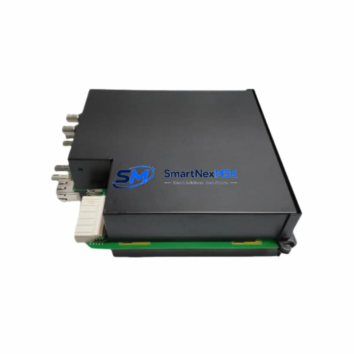
The GE Multilin R7I-MDM8-02-002 is an inter-relay communications module designed for the UR Series protection and control platform. In industrial power protection environments — substations, motor control centers, and high-voltage switchgear panels — this module serves as the backbone of inter-relay data exchange, enabling coordinated protection schemes, peer-to-peer communication, and real-time status sharing between UR-family relays. When this module fails or degrades, the entire protection coordination chain is at risk, making rapid, verified replacement a critical maintenance priority.
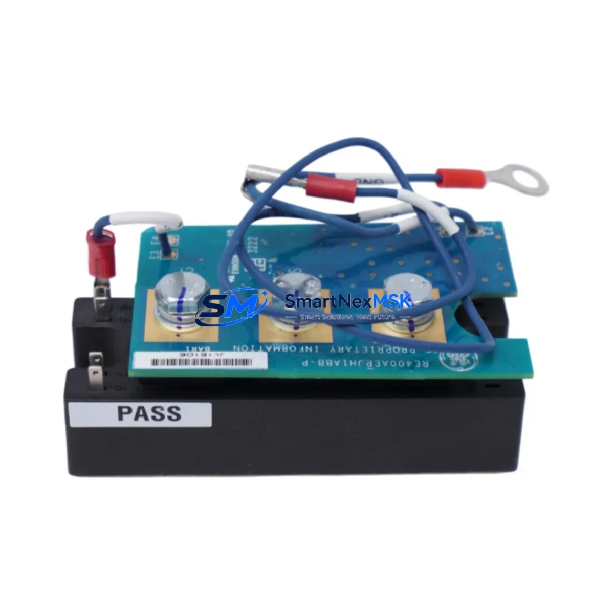
Sourced as an original GE Multilin component, each R7I-MDM8-02-002 unit we supply is pre-tested against factory electrical and communication specifications before dispatch. Our inventory is maintained specifically to support emergency replacement and planned maintenance cycles, with same-day processing available for in-stock orders. Every unit ships with a 12-month warranty covering manufacturing defects and functional performance.
Spare Maintenance Table
| Parameter | Specification / Detail |
|---|---|
| Part Number | R7I-MDM8-02-002 |
| Brand | GE Multilin |
| Series | UR Series (Universal Relay) |
| Module Type | Inter-Relay Communications Module |
| Communication Protocol | IEC 61850 GOOSE / Direct Inter-Relay (UR-to-UR) |
| Slot Compatibility | UR Series chassis — horizontal slot installation |
| Compatible Relay Families | C60, C70, D60, F60, G60, L90, M60, T60, T35, T60 |
| Operating Voltage | Per UR chassis backplane supply (typically 24–250 V DC) |
| Operating Temperature | -20°C to +60°C |
| Mounting | Modular plug-in, UR chassis rear slot |
| Application Environment | Substation, MCC, switchgear, power utility, industrial plant |
| Condition | Original / New — factory-spec tested |
| Warranty | 12 Months — covers manufacturing defects and functional performance |
| Lead Time | In-stock: same-day dispatch; ex-stock: 3–7 business days |
| Origin | United States (GE Multilin) |
Maintenance Planning for Continuous Operation
When a maintenance engineer identifies a fault or degraded performance in the R7I-MDM8-02-002, the replacement workflow should extend beyond the module itself. The UR Series chassis is a tightly integrated protection platform, and a communications module failure often signals stress on adjacent components that share the same backplane power rail and signal bus.
During a planned or emergency replacement of the R7I-MDM8-02-002, engineers should simultaneously inspect the UR Series power supply module (typically a 9A or 9B slot unit) for output voltage stability and ripple, as a degraded power supply is a common root cause of communications module failure. The UR chassis backplane itself should be visually inspected for burn marks, corrosion, or connector pin damage before seating the new module.
On the I/O side, the UR Series digital input/output modules (such as the 8D or 8L I/O cards) that feed status signals into the inter-relay communication scheme should be verified for correct signal levels and contact integrity. If the relay is part of a line differential or bus protection scheme, the UR Series communications processor module (e.g., 7SR or 9E series cards) handling IEC 61850 or DNP3 upstream SCADA traffic should also be tested for link continuity.
For sites using hardwired inter-relay signaling as a backup, the associated output relay contact modules and opto-isolated input modules in the same panel should be checked for contact wear and input threshold drift. Terminal blocks and DIN rail terminal assemblies connecting the UR relay to the inter-relay wiring harness are a frequent source of intermittent faults and should be re-torqued to specification during any module swap.
If the site uses a GE Multilin EnerVista UR Setup software configuration file, the replacement module must be confirmed to match the firmware revision expected by the relay’s configuration. Mismatched firmware between the R7I-MDM8-02-002 and the host relay can cause communication initialization failures even with a physically good module. Procurement engineers should note the relay firmware version from the nameplate or EnerVista before ordering to ensure compatibility.
For facilities maintaining a critical spares inventory, it is advisable to stock at least one R7I-MDM8-02-002 alongside a compatible UR Series CPU module, a spare power supply module, and a set of fiber optic patch cables used for the inter-relay channel — particularly for protection schemes where the communication path is the primary trip channel. Keeping these components together in a labeled, climate-controlled spare parts cabinet significantly reduces mean time to repair (MTTR) during unplanned outages.
Site Replacement Workflow
Step 1 — Isolation and Safety: Follow site LOTO (Lockout/Tagout) procedures. Confirm the relay is in test mode or the protection function is backed up by an alternate relay before removing the module. Document the current relay settings using EnerVista UR Setup.
Step 2 — Module Removal: Power down the UR chassis if required by site procedure. Carefully extract the R7I-MDM8-02-002 from its slot using the module ejector tabs. Inspect the backplane connector for bent pins or contamination.
Step 3 — Compatibility Verification: Confirm the replacement R7I-MDM8-02-002 matches the original part number exactly. Verify firmware compatibility with the host relay’s current firmware version. Do not substitute with a different MDM variant without engineering review, as channel count and protocol support differ between sub-variants.
Step 4 — Installation and Configuration: Seat the new module firmly until the ejector tabs click. Power up the chassis and observe the module status LEDs. Use EnerVista UR Setup to confirm the inter-relay communication channel is active and peer relays are visible on the network.
Step 5 — Functional Test: Perform a loopback or end-to-end communication test per the site’s protection testing procedure. Confirm GOOSE message reception at peer relays. Restore the relay to service and remove any test mode bypasses.
Step 6 — Documentation: Record the replacement in the site maintenance log, including the new module serial number, installation date, and test results. Update the spare parts inventory to trigger reorder of a replacement unit.
Spare Parts Support FAQ
Q: Is the R7I-MDM8-02-002 compatible with all UR Series relay models?
The R7I-MDM8-02-002 is designed for the GE Multilin UR Series platform and is compatible with relay models that support the inter-relay communications slot, including the C60, D60, F60, G60, L90, M60, T60, and related variants. Compatibility depends on the chassis slot configuration and firmware version. We recommend confirming the relay model and firmware revision before ordering. Our technical team can assist with compatibility verification at no charge.
Q: How is each unit tested before shipment?
Every R7I-MDM8-02-002 unit undergoes functional testing covering power-up initialization, communication channel activation, and electrical parameter verification against GE Multilin factory specifications. Units that do not pass all test criteria are not dispatched. A test report is available upon request for critical infrastructure applications.
Q: What does the 12-month warranty cover?
The 12-month warranty covers manufacturing defects, component failures, and functional non-conformance under normal operating conditions. It does not cover damage resulting from incorrect installation, overvoltage events, or physical mishandling. Warranty claims are processed with priority turnaround — replacement units are dispatched before the defective unit is returned in most cases, minimizing site downtime.
Q: Can you support long-term or recurring spare parts supply for this module?
Yes. We maintain ongoing inventory of the R7I-MDM8-02-002 and related UR Series modules to support both emergency replacement and planned maintenance programs. Procurement engineers can request a standing supply agreement or blanket order arrangement to ensure guaranteed availability and fixed pricing over a 12–24 month horizon. Contact our team to discuss volume pricing and lead time commitments.
© 2026 SMARTNEXMSK. All rights reserved.
Original Source: https://smartnexmsk.com
Contact: sales@smartnexmsk.com | +86 18259474341