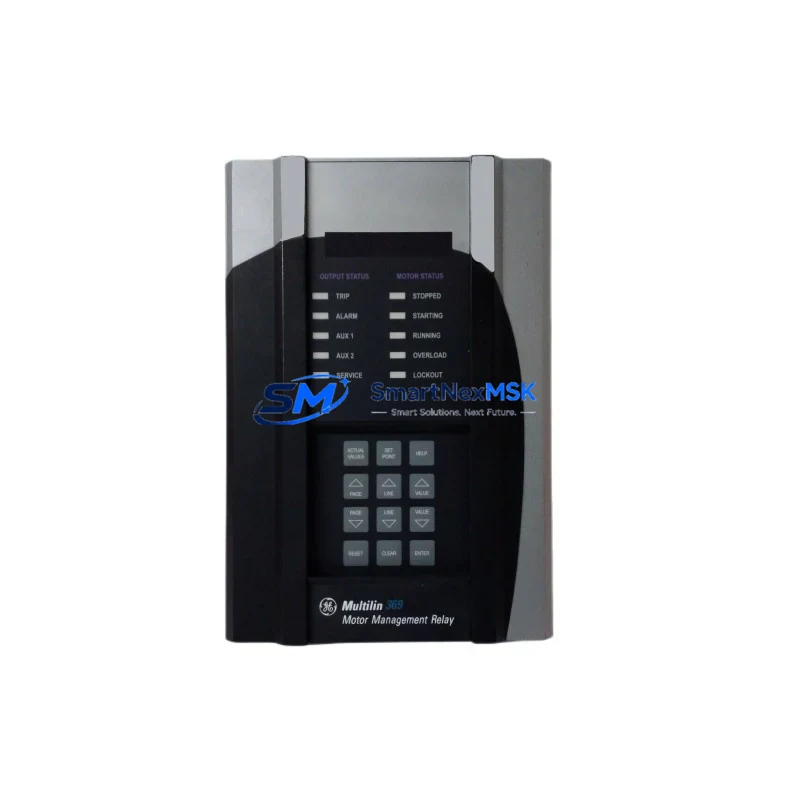
GE Multilin 369-HI-R-M-0-0-H-E Retrofit-Ready Motor Relay for 369 Series Control Systems
The GE Multilin 369-HI-R-M-0-0-H-E is a high-performance motor management relay engineered for seamless integration into existing 369 Series control architectures. Whether you are replacing an end-of-life unit on a legacy production line, upgrading a control cabinet that has been in continuous service for over a decade, or migrating from an older protection scheme to a more capable platform, this relay delivers the compatibility, reliability, and field-proven performance that industrial automation engineers demand.
Sourced directly from authorized distribution channels and subject to full functional testing prior to shipment, each unit is backed by a 12-month warranty and is ready for immediate deployment in motor protection, control, and monitoring applications across oil and gas, water treatment, mining, pulp and paper, and heavy manufacturing environments.
Upgrade Compatibility Table
| Parameter | Details |
|---|---|
| SKU / Part Number | 369-HI-R-M-0-0-H-E |
| Brand / Manufacturer | GE Multilin (now GE Grid Solutions) |
| Product Series | 369 Motor Management Relay Series |
| Common Replaced Models | 369-HI-R-M-0-0-H-E (prior firmware revisions), 369-LO-R-M-0-0-H-E, 369-HI-R-D-0-0-H-E |
| Mounting / Form Factor | Panel-mount, standard 369 Series cutout; no chassis modification required |
| Communication Interface | RS-485 Modbus RTU; optional DNP3 / IEC 60870-5-103 depending on order suffix |
| Power Supply Input | 85–265 V AC/DC universal auxiliary power (H suffix) |
| CT Input Compatibility | 1 A or 5 A secondary; confirm existing CT ratio before installation |
| Terminal Wiring | Screw-terminal block; pin-compatible with 369 Series wiring harness |
| Retrofit Commissioning | EnerVista 369 Setup Software required for parameter upload/download |
| Firmware Compatibility | Settings files from earlier 369 firmware versions are importable with minor review |
| Warranty | 12 months from date of shipment |
Retrofit Planning for Existing Automation Systems
A successful retrofit of the 369-HI-R-M-0-0-H-E begins well before the unit arrives on site. Engineers should start by auditing the existing control cabinet layout, confirming the auxiliary power supply rating, and verifying that the installed current transformers match the relay’s 1 A or 5 A CT input specification. In many legacy installations, the auxiliary power is drawn from a shared 24 V DC bus fed by a GE Multilin PSU-24VDC or equivalent DIN-rail power supply module; confirming that this supply has sufficient headroom for the new relay’s inrush current is a critical pre-commissioning step.
Terminal wiring on the 369 Series uses a labeled screw-terminal block arrangement that is consistent across the product family, which significantly simplifies like-for-like replacement. However, engineers should photograph and document the existing wiring before disconnection, paying particular attention to the trip output relay contacts, the analog output loop (4–20 mA), and the RS-485 communication port termination. If the existing installation uses a GE Multilin 469 Motor Management Relay or a GE Multilin 239 Motor Protection Relay elsewhere in the same switchgear lineup, the Modbus register map differences between product families must be accounted for in the SCADA or DCS configuration.
For sites running a GE Fanuc Series 90-30 PLC or a GE PACSystems RX3i as the host controller, the Modbus RTU polling configuration in the PLC program will need to be verified against the 369’s register map. If the legacy system used a GE Multilin SR750 Feeder Protection Relay or SR760 in the same protection scheme, ensure that the inter-relay communication logic and trip bus wiring are reviewed before energization. Sites that have migrated to EtherNet/IP or PROFIBUS DP should note that the 369-HI-R-M-0-0-H-E communicates natively over RS-485 Modbus RTU; a GE Multilin F485 RS-485 to Fiber Converter or a third-party protocol gateway may be required to bridge to higher-level networks.
I/O expansion requirements should also be assessed at the planning stage. If the motor being protected drives a critical process and requires additional digital inputs for thermal sensor monitoring or vibration interlock, the 369’s onboard RTD inputs (up to 12 RTDs depending on order code) may eliminate the need for a separate GE Multilin RTD Module or external temperature scanner. For applications where the 369 is installed alongside a GE Multilin 750/760 Feeder Protection Relay in a common MCC bucket, confirm that the shared trip bus wiring and the common alarm annunciator panel are compatible with the new relay’s output contact ratings.
HMI integration is another area that requires attention during retrofit planning. If the site uses a GE iFIX SCADA or a Wonderware InTouch HMI with existing 369 Series faceplates, the Modbus address mapping should be validated against the new unit’s firmware version to ensure that all motor status, protection pickup, and fault log screens continue to function correctly after the swap. EnerVista 369 Setup Software, available from GE Grid Solutions, provides a settings comparison tool that highlights differences between the saved settings file and the factory defaults of the replacement unit, which is invaluable for catching configuration drift before the motor is restarted.
Downtime Control During System Migration
Minimizing unplanned downtime during a 369-HI-R-M-0-0-H-E replacement requires a structured approach that protects the original program logic and maintains field control continuity throughout the swap. The recommended procedure is to use EnerVista 369 Setup Software to upload and save the complete settings file from the outgoing relay before any power is removed. This file captures all protection setpoints, CT ratios, RTD assignments, output relay configurations, and communication parameters, and serves as the authoritative restore point for the replacement unit.
Once the settings file is secured, the motor should be taken to a safe, de-energized state following the site’s lockout/tagout procedure. The replacement relay can then be installed in the existing panel cutout without modification, and the terminal wiring reconnected using the pre-documented wiring photographs. After power is restored to the relay’s auxiliary supply, the saved settings file is downloaded to the new unit via the front RS-232 port or the rear RS-485 port using EnerVista software, and a full functional test is performed before the motor is returned to service.
For critical processes where even a brief interruption is costly, it is advisable to pre-configure the replacement relay on the bench using a copy of the settings file before the scheduled maintenance window. This approach reduces the in-cabinet commissioning time to the wiring reconnection and functional verification steps, typically bringing total downtime for a straightforward like-for-like replacement to under two hours. All units supplied by SMARTNEXMSK are pre-tested and shipped with a factory test report, further reducing the risk of commissioning delays caused by infant-failure defects.
Retrofit Support FAQ
Q1: Is the 369-HI-R-M-0-0-H-E a direct drop-in replacement for earlier 369 Series variants?
A: Yes, for the vast majority of installations. The 369 Series maintains a consistent panel cutout, terminal block layout, and Modbus register map across its production history. Minor firmware differences may affect the behavior of advanced protection functions; a settings file comparison using EnerVista 369 Setup Software is recommended before returning the motor to service.
Q2: What commissioning steps are required after installing the replacement relay?
A: After wiring reconnection, restore the saved settings file via EnerVista software, verify CT ratio and RTD assignments, confirm Modbus communication with the host PLC or DCS, perform an output relay contact test, and conduct a staged trip test if the process permits. Document all commissioning results for the site maintenance record.
Q3: Can the existing RS-485 wiring and Modbus configuration be reused without modification?
A: In most cases, yes. The 369-HI-R-M-0-0-H-E uses the same RS-485 Modbus RTU interface and register map as previous 369 Series units. Confirm the baud rate, parity, and device address settings match the host controller configuration. If the site uses a protocol gateway or fiber converter, verify that the gateway’s Modbus polling parameters are unchanged.
Q4: What does the 12-month warranty cover, and what is the return process?
A: The 12-month warranty covers manufacturing defects and functional failures under normal operating conditions from the date of shipment. Units that fail within the warranty period should be returned with a completed RMA form and the original test report. SMARTNEXMSK will repair or replace the unit at no charge and return it with a new test report. Contact sales@smartnexmsk.com or +86 18259474341 to initiate a warranty claim.
© 2026 SMARTNEXMSK. All rights reserved.
Original Source: https://smartnexmsk.com
Contact: sales@smartnexmsk.com | +86 18259474341