GE Multilin UR 7BH Maintenance-Ready Spare UR Series Automation
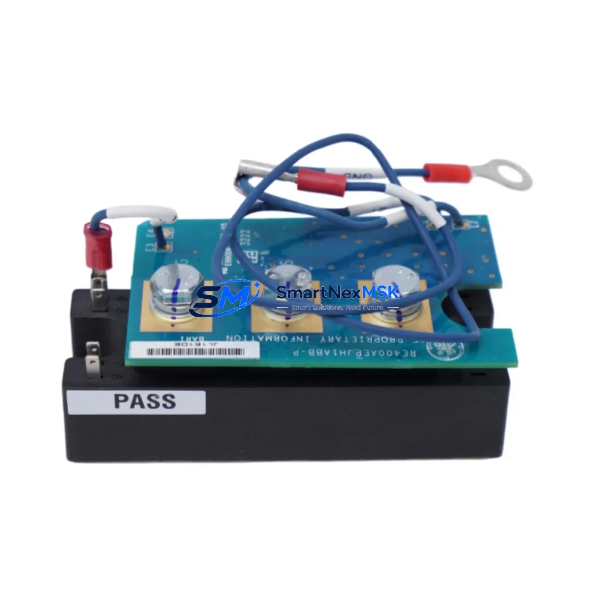
The GE Multilin UR 7BH is an original communication module engineered for the UR Series of protection relays — a platform widely deployed across power generation, transmission substations, industrial switchgear, and utility distribution networks. When a UR Series relay loses its communication interface, the entire protection and SCADA visibility chain is interrupted. Sourcing a verified, tested UR 7BH spare is the fastest path to restoring full system functionality and minimising unplanned downtime.
This module supports the IEC 61850, DNP3, and Modbus communication protocols that are standard in modern substation automation architectures. Maintenance engineers and procurement teams working with GE Multilin UR6, UR7, and UR8 chassis platforms will find the UR 7BH a direct, plug-compatible replacement that requires no firmware re-flashing when the relay configuration is backed up prior to the swap. Our units are sourced from authorised supply chains, individually inspected, and shipped with a 12-month warranty covering manufacturing defects and functional performance.
Spare Maintenance Table
| Parameter | Specification |
|---|---|
| Part Number / SKU | UR 7BH |
| Brand | GE Multilin |
| Series | UR Series (UR6 / UR7 / UR8 chassis) |
| Module Type | Communication Module |
| Supported Protocols | IEC 61850, DNP3, Modbus RTU/TCP, GOOSE |
| Interface | Fibre optic / RJ-45 Ethernet (model-dependent) |
| Operating Voltage | Per UR chassis backplane supply (24–250 V DC typical) |
| Operating Temperature | –40 °C to +85 °C |
| Mounting | UR Series modular slot (hot-swap capable with relay de-energised) |
| Compatibility | GE Multilin 745, 750, 760, 769, 850, 869, 489, T60, L90, C60, D60 |
| Application Environment | Substations, power plants, industrial switchgear, MV/HV protection panels |
| Maintenance Recommendation | Inspect every 24 months; replace on communication fault or firmware incompatibility |
| Warranty | 12 Months — covers manufacturing defects and functional performance |
| Origin | USA |
| Shipping | Tested before dispatch; worldwide express available |
Maintenance Planning for Continuous Operation
A communication module failure in a UR Series relay rarely occurs in isolation. During a planned or emergency replacement of the UR 7BH, a thorough maintenance engineer will simultaneously audit the surrounding components to prevent repeat call-outs and ensure the protection system is fully restored.
Begin with the UR Series power supply module (such as the 7A or 7B power card) — a degraded DC/DC converter can cause intermittent communication resets that mimic a faulty 7BH. Verify the backplane voltage rails are within tolerance before condemning the communication card. Next, inspect the UR chassis backplane itself for oxidised connector pins or cracked PCB traces, particularly in installations exposed to high humidity or vibration.
On the I/O side, check the UR digital input/output modules (e.g., 8D or 8L cards) for contact wear or wiring termination issues at the terminal blocks. Loose or corroded terminals on CT and VT secondary circuits can introduce noise that stresses the communication interface. If the relay is part of a busbar or transformer protection scheme, also verify the inter-relay GOOSE communication links — a misconfigured or broken fibre patch cord between UR relays is a common root cause of apparent module faults.
For installations using serial communications, inspect the RS-485 signal isolator and any protocol converters in the SCADA chain. A failed isolator can back-feed voltage onto the relay’s communication port and damage the 7BH. Where Ethernet connectivity is used, check the managed Ethernet switch port configuration, VLAN settings, and cable integrity. Substation-grade switches from the same protection panel should be tested for port errors and CRC counts.
Finally, review the HMI or operator workstation connection to confirm that the SCADA polling rate and timeout settings are compatible with the replacement module’s firmware version. Updating the relay’s EnerVista UR Setup configuration file before re-commissioning will prevent address conflicts and ensure the new UR 7BH is recognised immediately by the control system.
Site Replacement Workflow
Step 1 — Pre-replacement backup: Connect a laptop running EnerVista UR Setup and export the full relay settings file (.urs). Record the existing communication parameters: IP address, DNP3 address, IEC 61850 IED name, and GOOSE dataset configuration.
Step 2 — Safe isolation: Coordinate with the control room to place the relay in test mode or inhibit SCADA alarms. De-energise the UR chassis following the site’s lockout/tagout procedure. Do not attempt hot-swap with the chassis energised unless the specific UR model supports it.
Step 3 — Module removal and installation: Release the UR 7BH retaining screws, slide the module out, and insert the replacement unit into the same slot. Torque retaining screws to the manufacturer’s specification. Reconnect fibre or Ethernet cables, ensuring bend radius limits are observed for fibre connections.
Step 4 — Configuration restore: Re-energise the chassis and upload the saved settings file via EnerVista. Verify the communication status LED on the new 7BH shows active link. Confirm SCADA connectivity by checking live data points at the master station.
Step 5 — Functional test and handover: Perform a loop test on digital inputs and outputs, verify protection element status, and confirm event logging is active. Document the replacement in the site maintenance register and update the spare parts inventory.
This workflow typically achieves full system restoration within 2–4 hours for a prepared maintenance team, significantly reducing the mean time to repair (MTTR) compared to waiting for OEM field service.
Spare Parts Support FAQ
Q1: Is the UR 7BH compatible with all UR Series relay models?
The UR 7BH is designed for the GE Multilin UR modular platform and is compatible with a wide range of UR Series relays including the 745, 750, 760, 769, 850, 869, 489, T60, L90, C60, and D60. Compatibility depends on the chassis slot type and firmware version. We recommend confirming your relay’s order code and firmware revision before ordering. Our technical team can assist with compatibility verification at no charge.
Q2: What testing is performed before shipment?
Every UR 7BH unit undergoes functional power-on testing and communication port verification before dispatch. Units are inspected for physical damage, connector integrity, and firmware version. A test report is available on request. All units are packed in anti-static ESD-safe packaging with foam protection to prevent transit damage.
Q3: How should I manage UR 7BH inventory for a multi-site operation?
For operations with five or more UR Series relays across multiple sites, we recommend maintaining at least one UR 7BH spare per communication protocol variant in use (e.g., one IEC 61850 fibre unit and one DNP3 Ethernet unit). A centralised spare parts store with documented relay-to-spare mapping reduces emergency procurement lead times from weeks to hours. We offer volume pricing and reserved stock agreements for maintenance contractors and utilities.
Q4: What does the 12-month warranty cover?
The 12-month warranty covers manufacturing defects, component failures under normal operating conditions, and functional performance as specified. It does not cover damage caused by incorrect installation, overvoltage events, or physical mishandling. In the event of a warranty claim, we provide advance replacement shipping to minimise your downtime — you return the faulty unit after receiving the replacement.
© 2026 SMARTNEXMSK. All rights reserved.
Original Source: https://smartnexmsk.com
Contact: sales@smartnexmsk.com | +86 18259474341