GE UR 67H Retrofit-Ready Directional Overcurrent Module for UR Series Control Systems
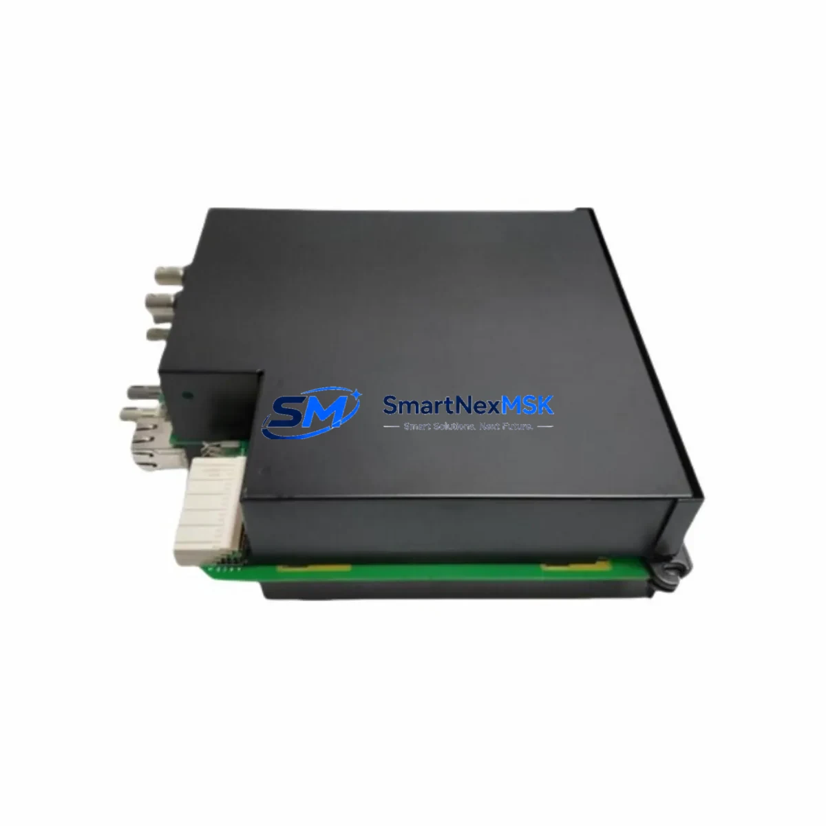
The GE UR 67H is a directional overcurrent protection relay module engineered for seamless integration into GE’s Universal Relay (UR) platform. As legacy protection systems age and OEM support windows close, the UR 67H has become a critical retrofit component for utilities, industrial plants, and substation operators seeking to extend the operational life of their existing UR Series control infrastructure without a full panel replacement. Whether you are replacing a failed unit, upgrading from an earlier UR generation, or migrating from a third-party protection relay platform, the UR 67H delivers verified compatibility with the UR chassis backplane, standardized terminal wiring, and the IEC 61850 / DNP3 communication protocols already in use across most modern substations.
Sourced directly from authorized distribution channels and subject to full functional testing prior to shipment, each UR 67H unit supplied by SMARTNEXMSK is backed by a 12-month warranty covering manufacturing defects and operational failures under normal service conditions. Stock is maintained on-hand to support urgent replacement orders, minimizing unplanned downtime for critical protection circuits.
Upgrade Compatibility Table
| Parameter | Detail |
|---|---|
| Compatible Platform | GE UR Series (UR-6, UR-7, UR-8 chassis generations) |
| Module Function | Directional Overcurrent Protection (67 / 67N elements) |
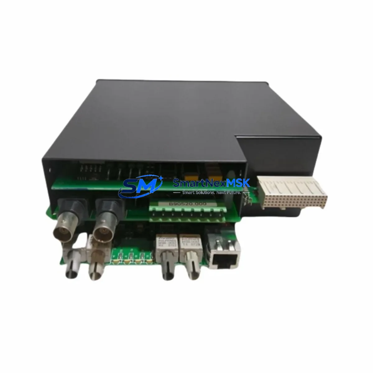
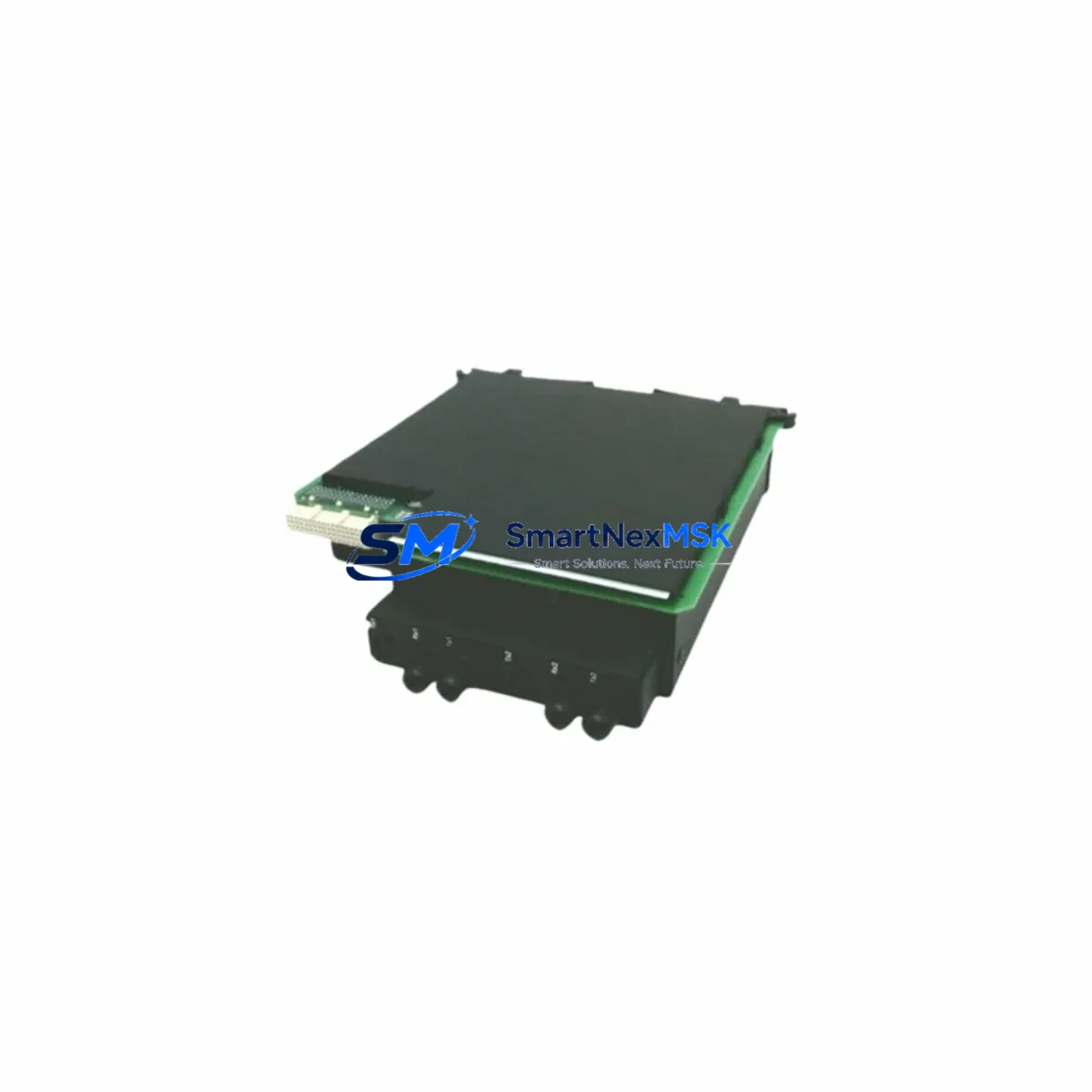
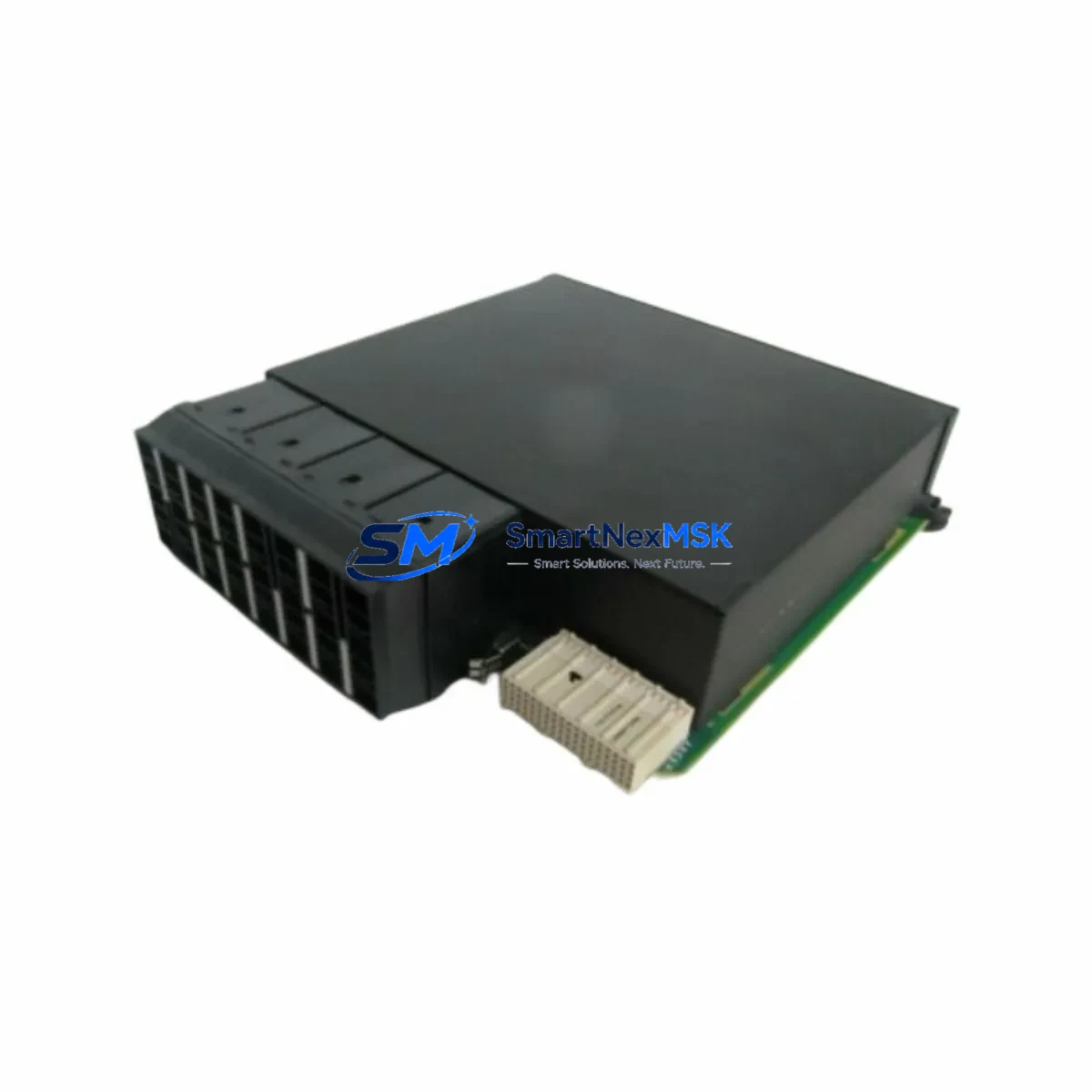
| Backplane Interface | UR standard rear-bus connector; plug-and-play slot replacement |
| Terminal Wiring | Compatible with existing UR terminal block layouts; no rewiring required in most installations |
| Communication Protocols | IEC 61850 GOOSE, DNP3, Modbus RTU/TCP — matches UR platform standard |
| Power Supply Requirement | 24–250 V DC / 120–240 V AC (confirm with UR chassis PSU rating) |
| Replacement Scope | Direct drop-in for discontinued UR 67H units; compatible with UR 67, 67N, 67G variants upon firmware verification |
| Firmware / Settings Migration | Settings file (.urs) exportable via EnerVista UR Setup software; re-import after module swap |
| Installation Requirement | UR chassis slot alignment; torque terminal screws to OEM spec (0.5–0.6 N·m) |
| Commissioning Note | Verify CT/VT polarity, directional element characteristic angle, and pickup thresholds post-swap |
| Warranty | 12 months from date of shipment; covers manufacturing defects and functional failures |
Retrofit Planning for Existing Automation Systems
A successful UR 67H retrofit begins well before the module arrives on site. Engineers should start by auditing the existing UR chassis — confirming the backplane revision, available slot positions, and the firmware version running on the UR CPU module (such as the GE UR CPU-3 or CPU-4) to ensure the 67H firmware image is compatible. The UR platform’s modular architecture means the 67H slots directly into the protection I/O bay without disturbing adjacent modules, including installed GE UR CT/VT DSP modules or UR analog input modules that handle current and voltage sensing.
Terminal wiring should be documented before removal of the legacy unit. In most UR installations, the rear terminal block remains fixed to the chassis, so the physical wiring to CT circuits, VT circuits, binary inputs, and output relay contacts does not need to be disturbed. However, engineers should verify that the CT shorting links are engaged before removing the old module to prevent open-circuit CT hazards. The GE UR binary I/O module assignments and the UR communications processor module (handling IEC 61850 or DNP3 links to the SCADA system) remain unaffected by a single-slot module swap.
Settings migration is handled through GE’s EnerVista UR Setup software. Export the full settings file (.urs) from the existing relay before removal, then import it into the replacement UR 67H after installation. Review the directional element characteristic angle (typically MTA/RCA settings), pickup current thresholds, time-overcurrent curves (IEEE/IEC curve selections), and any GOOSE message subscriptions configured for inter-relay communication. If the plant also operates GE UR 87T transformer differential modules or UR 21 frequency protection modules in the same chassis, confirm that the GOOSE dataset mappings remain consistent after the swap.
For sites migrating from older GE MIFII or Multilin SR series relays to the UR platform, the UR 67H represents a significant functional upgrade — adding IEC 61850 native support, enhanced oscillography recording, and expanded setting group capability. In these cross-platform migrations, the GE UR communications module (CM) and a UR fiber optic interface module are commonly added alongside the 67H to complete the protocol migration from legacy RS-485 Modbus to IEC 61850 over Ethernet. A GE UR test module or portable relay test set (such as the Omicron CMC series) should be used to perform secondary injection testing and verify directional element operation before returning the protection circuit to service.
Downtime Control During System Migration
Minimizing protection system downtime is the primary operational constraint in any UR 67H replacement project. The recommended approach is a hot-standby swap sequence: coordinate with the system operator to place the protected feeder or transformer on backup protection (bus differential or upstream overcurrent) before de-energizing the relay panel. This preserves system protection continuity while the UR 67H is replaced.
The module swap itself — removing the old unit, seating the replacement UR 67H, and re-engaging the backplane connector — typically takes under 15 minutes for a trained technician. The majority of commissioning time is spent on settings verification and secondary injection testing. To compress this window, prepare the settings file import and the test plan in advance. Use the EnerVista UR Setup offline mode to pre-load and validate the settings file on a laptop before arriving on site, so the import step is a single operation during the maintenance window.
Preserve the original program logic and HMI display assignments by exporting the full relay configuration — including custom logic (FlexLogic equations), virtual outputs, and SCADA point mappings — before the swap. If the substation HMI (such as a GE iFIX SCADA or third-party HMI connected via DNP3) uses relay-specific point addresses, verify that the replacement UR 67H retains the same DNP3 object assignments. In most cases, because the settings file is fully re-imported, HMI screens and SCADA alarm points require no modification. After commissioning, perform a live-load check to confirm directional element polarization and metering accuracy before releasing the feeder back to normal protection.
Retrofit Support FAQ
Q1: Is the UR 67H a direct drop-in replacement for my existing GE UR directional overcurrent module?
In the vast majority of UR Series installations, yes. The UR 67H uses the standard UR backplane connector and rear terminal block, so physical installation is a slot-for-slot swap. You should verify the chassis generation (UR-6 vs. UR-7/8) and confirm firmware compatibility using EnerVista UR Setup before ordering. SMARTNEXMSK can assist with compatibility verification based on your chassis serial number and existing module part number.
Q2: What commissioning steps are required after installing the replacement UR 67H?
After seating the module and importing the settings file, perform the following: (1) verify CT and VT polarity at the relay terminals; (2) confirm the directional element characteristic angle and pickup thresholds match the protection coordination study; (3) conduct secondary injection testing to verify 67 and 67N element operation; (4) check GOOSE subscriptions and DNP3 / IEC 61850 communication links to the SCADA system; (5) perform a live-load metering check. Full commissioning typically takes 2–4 hours depending on site complexity.
Q3: Can the UR 67H be used to replace relays from other manufacturers, such as SEL or ABB REF series?
The UR 67H is a GE UR platform module and requires a GE UR chassis — it cannot be installed in a non-GE rack. However, for sites migrating from SEL-351 or ABB REF615 directional overcurrent relays to the GE UR platform, the UR 67H provides equivalent 67/67N protection functionality. Migration projects of this type require new terminal wiring, a UR chassis, and a UR CPU module, and SMARTNEXMSK can supply the full bill of materials for such upgrades.
Q4: What does the 12-month warranty cover, and what is the process for a warranty claim?
The 12-month warranty covers manufacturing defects and functional failures under normal operating conditions from the date of shipment. It does not cover damage caused by incorrect installation, overvoltage events, or physical mishandling. To initiate a warranty claim, contact SMARTNEXMSK at sales@smartnexmsk.com with your order number, a description of the failure, and any available relay event records or oscillography files. Replacement units are dispatched from stock upon claim approval, minimizing your system downtime.
© 2026 SMARTNEXMSK. All rights reserved.
Original Source: https://smartnexmsk.com
Contact: sales@smartnexmsk.com | +86 18259474341