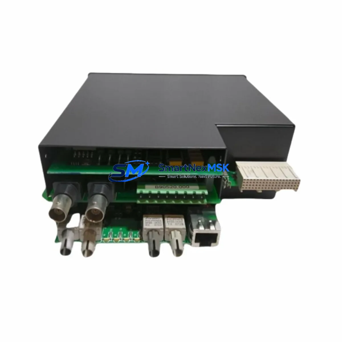
GE UR-SHH Retrofit-Ready Relay Module for UR Series Control Systems
The GE UR-SHH is a high-performance protection relay module engineered for seamless integration into GE’s Universal Relay (UR) Series platform. As aging protection relay infrastructure reaches end-of-life across substations, power generation facilities, and industrial control systems, the UR-SHH provides a verified, drop-in compatible upgrade path that eliminates the need for full panel redesign or control system replacement. Whether you are replacing a discontinued UR-series card, expanding I/O capacity in an existing relay chassis, or migrating from legacy electromechanical protection schemes, the UR-SHH delivers the reliability and compatibility that critical infrastructure demands.
Sourced directly from authorized distribution channels and subject to full functional testing prior to dispatch, every UR-SHH unit shipped by SMARTNEXMSK is backed by a 12-month warranty covering manufacturing defects and operational failures under normal service conditions. Inventory is maintained in-stock for immediate fulfillment via DHL Express or FedEx International Priority, with typical lead times of 3–7 business days to most global destinations.
Upgrade Compatibility Table
| Parameter | Details |
|---|---|
| Compatible Platform | GE UR Series (Universal Relay) — C30, C60, C70, D30, D60, F35, F60, L30, L60, L90, M60, N60, T35, T60 |
| Module Slot Interface | UR-series rear-mount backplane slot; standard UR module form factor |
| Communication Compatibility | IEC 61850 GOOSE, DNP3, Modbus RTU/TCP, IEC 60870-5-103/104 (platform-dependent) |
| Power Supply Requirement | Verify chassis PSU capacity before installation; UR-series power modules (e.g., UR-PSH, UR-PSL) must meet aggregate module load |
| Replacement Recommendation | Direct replacement for discontinued UR-SHH variants; confirm firmware revision compatibility with relay CPU module |
| Commissioning Notes | Re-map I/O assignments in EnerVista UR Setup software; validate protection settings file; test trip/close outputs before energizing |
| Warranty | 12 months from date of shipment — covers manufacturing defects and functional failures under rated operating conditions |
Retrofit Planning for Existing Automation Systems
Successful integration of the UR-SHH into an existing protection scheme begins well before the module arrives on site. Engineers responsible for the retrofit should start by auditing the current UR relay chassis configuration — identifying which backplane slots are occupied, confirming the installed UR CPU module firmware version, and reviewing the existing settings file exported from EnerVista UR Setup. The UR-SHH must be installed in a slot that matches its designated function within the relay’s I/O architecture; incorrect slot placement will result in the relay flagging a hardware mismatch alarm.
Power budget verification is a non-negotiable step. The UR-series chassis relies on dedicated UR power supply modules — typically the UR-PSH (high-range DC input) or UR-PSL (low-range DC input) — to distribute regulated power across all installed modules. Adding or replacing a module changes the aggregate current draw on the backplane bus. Before installation, calculate the total module power consumption against the rated output of the installed power supply module and confirm adequate headroom exists. Failure to do so risks nuisance trips or PSU overload during high-demand switching events.
Terminal wiring adaptation is another critical checkpoint. The UR-SHH uses the standard UR rear-terminal block layout, but field wiring from the previous module must be verified against the new module’s terminal assignment diagram. In many retrofit scenarios — particularly where the original module was installed under an older firmware baseline — terminal functions may have been remapped through software configuration rather than physical rewiring. Cross-reference the existing wiring schedule against the UR-SHH terminal diagram before disconnecting any conductors.
For sites running IEC 61850-based protection schemes, the GOOSE message subscriptions and publications configured in the UR IEC 61850 configurator must be reviewed and updated to reflect the new module’s logical node assignments. Similarly, if the relay communicates upstream to a SCADA system via DNP3 or Modbus TCP, the data point mapping file should be exported, backed up, and re-validated post-installation. Sites using GE’s Multilin SR series relays in parallel protection schemes should also verify that inter-relay communication links — particularly those using UR direct I/O or fiber-optic differential channels — remain intact after the module swap.
Where the retrofit involves migrating from an older GE Multilin 489, 369, or 339 motor protection relay to the UR platform, additional engineering effort is required to translate legacy protection logic into UR-compatible FlexLogic equations. The UR FlexLogic programmable logic engine provides equivalent functionality to the fixed-function logic of older Multilin relays, but the translation is not automatic — each protection element, output relay assignment, and LED indicator mapping must be manually re-created and tested. SMARTNEXMSK recommends maintaining the legacy relay in service in a monitoring-only mode during the parallel commissioning period to provide a fallback reference.
HMI integration should also be addressed during the planning phase. If the substation or plant uses a GE iFIX SCADA or third-party HMI platform with pre-built UR relay faceplates, the faceplate data tags must be updated to reflect any changes in register addresses or data object paths introduced by the new module. For sites using GE EnerVista Viewpoint Monitoring, the device template may need to be refreshed to include the UR-SHH’s specific data model.
Downtime Control During System Migration
Minimizing protection system downtime during a UR-SHH module replacement requires a structured, pre-tested execution plan. The recommended approach is a hot-standby swap procedure: before removing the existing module, export the complete relay settings file from EnerVista UR Setup, document all active alarms and event log entries, and photograph the existing terminal wiring. This creates a verified restore point that allows the relay to be returned to its pre-swap state within minutes if an unexpected issue arises during commissioning.
Where the protection zone cannot be taken out of service for an extended period, coordinate with the operations team to schedule the swap during a planned maintenance window — ideally during a low-load period when the protected asset (transformer, feeder, motor, or generator) can be isolated without impacting production continuity. For critical protection applications, arrange for a temporary protection relay — such as a portable GE Multilin 750/760 feeder protection relay — to provide backup coverage during the swap window.
Once the UR-SHH is physically installed and the settings file has been loaded, perform a complete I/O functional test using the relay’s built-in test mode before re-energizing the protection zone. Verify each digital input, output relay, and analog measurement channel against the design specification. Confirm that all GOOSE subscriptions are active and that the relay’s self-test diagnostics report no hardware faults. Only after a clean functional test should the protection zone be re-energized and the relay placed back in service.
Throughout the migration, maintain a detailed commissioning record documenting each test step, the engineer responsible, the test result, and the timestamp. This record serves as the formal acceptance document for the retrofit and provides the baseline reference for future maintenance activities. All UR-SHH units supplied by SMARTNEXMSK include a factory test report confirming that the module passed full functional verification prior to shipment.
Retrofit Support FAQ
Q1: Is the UR-SHH a direct drop-in replacement for the original GE UR-SHH module?
Yes, the UR-SHH is designed to the same mechanical and electrical specification as the original GE Grid Solutions UR-SHH module. It installs into the same backplane slot, uses the same terminal block layout, and is recognized by the UR relay CPU without requiring hardware modification. However, we recommend verifying firmware compatibility between the replacement module and the installed CPU module version using EnerVista UR Setup before installation.
Q2: What commissioning steps are required after installing the UR-SHH?
After physical installation, reload the relay settings file via EnerVista UR Setup and perform a full I/O functional test. Verify all digital inputs and output relay assignments, confirm communication link status (IEC 61850, DNP3, or Modbus as applicable), and check that the relay’s self-diagnostics report no faults. For differential protection applications, re-verify CT ratio and polarity settings before re-energizing the protected zone.
Q3: How do I verify wiring compatibility between the old module and the UR-SHH?
Compare the existing field wiring schedule against the UR-SHH terminal assignment diagram provided in the GE UR Hardware Manual. Pay particular attention to analog input channels (CT and VT connections), digital input voltage thresholds, and output relay contact ratings. If the original module was configured with non-standard terminal assignments via software remapping, review the settings file to identify any deviations from the default terminal layout before disconnecting field wiring.
Q4: What does the 12-month warranty cover, and what is the claims process?
The 12-month warranty covers manufacturing defects and functional failures under rated operating conditions from the date of shipment. It does not cover damage resulting from incorrect installation, overvoltage events, or operation outside the module’s rated environmental specifications. To initiate a warranty claim, contact SMARTNEXMSK at sales@smartnexmsk.com with the order reference number, a description of the fault, and any available diagnostic data from the relay event log. Replacement units are dispatched within 5 business days of claim approval.
© 2026 SMARTNEXMSK. All rights reserved.
Original Source: https://smartnexmsk.com
Contact: sales@smartnexmsk.com | +86 18259474341