GE UR6NH Retrofit-Ready Digital Inputs Module for UR Series Control Systems
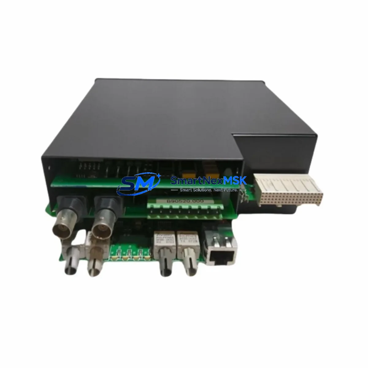
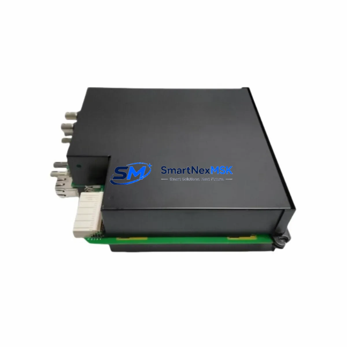
The GE UR6NH is a digital inputs I/O module engineered for the GE UR Series protection relay platform — one of the most widely deployed numerical relay families in substation automation, feeder protection, and motor management applications worldwide. As legacy UR Series installations age and original spare parts become increasingly difficult to source, the UR6NH has become a critical component in retrofit programs, panel upgrades, and emergency restoration projects across power utilities, industrial plants, and EPC contractors.
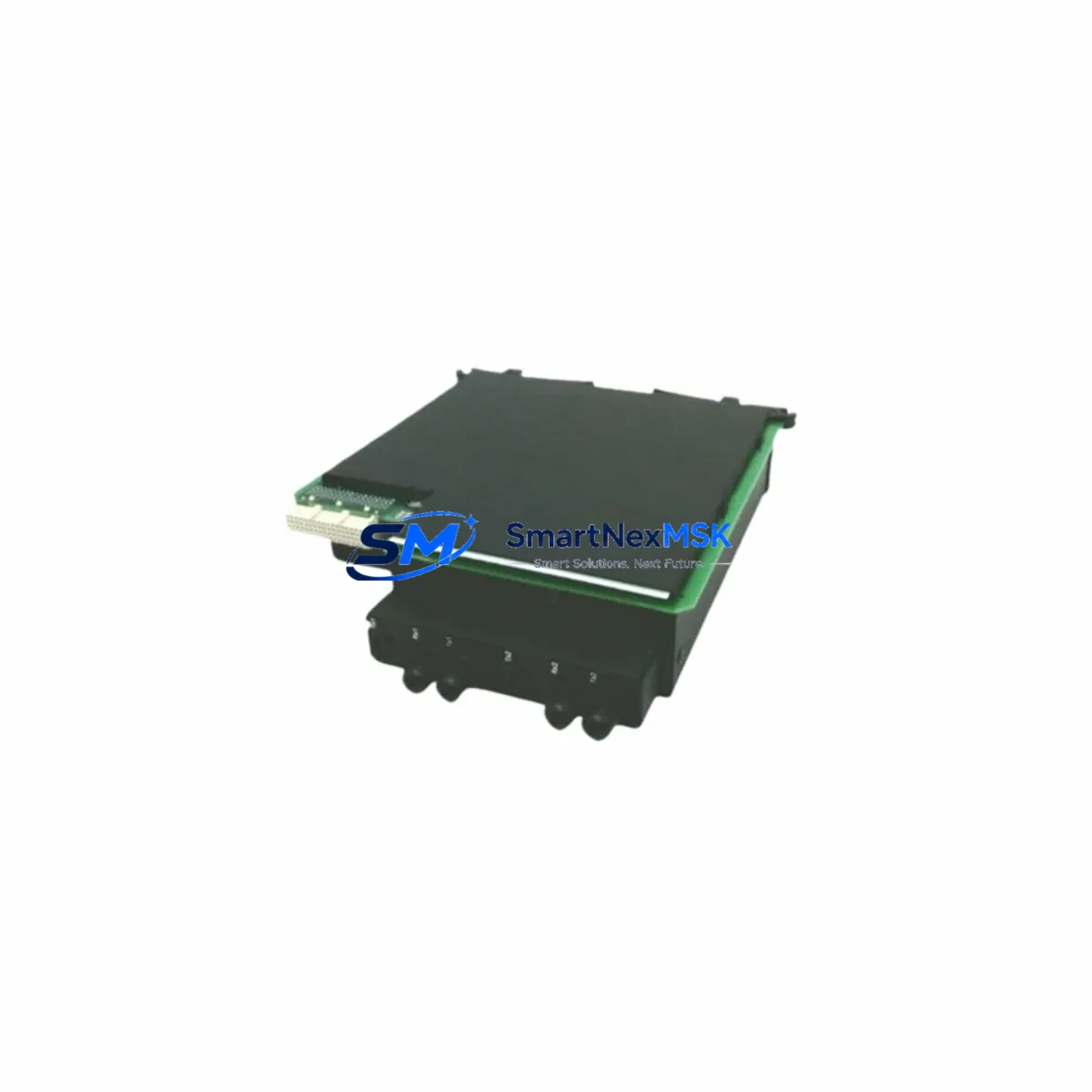
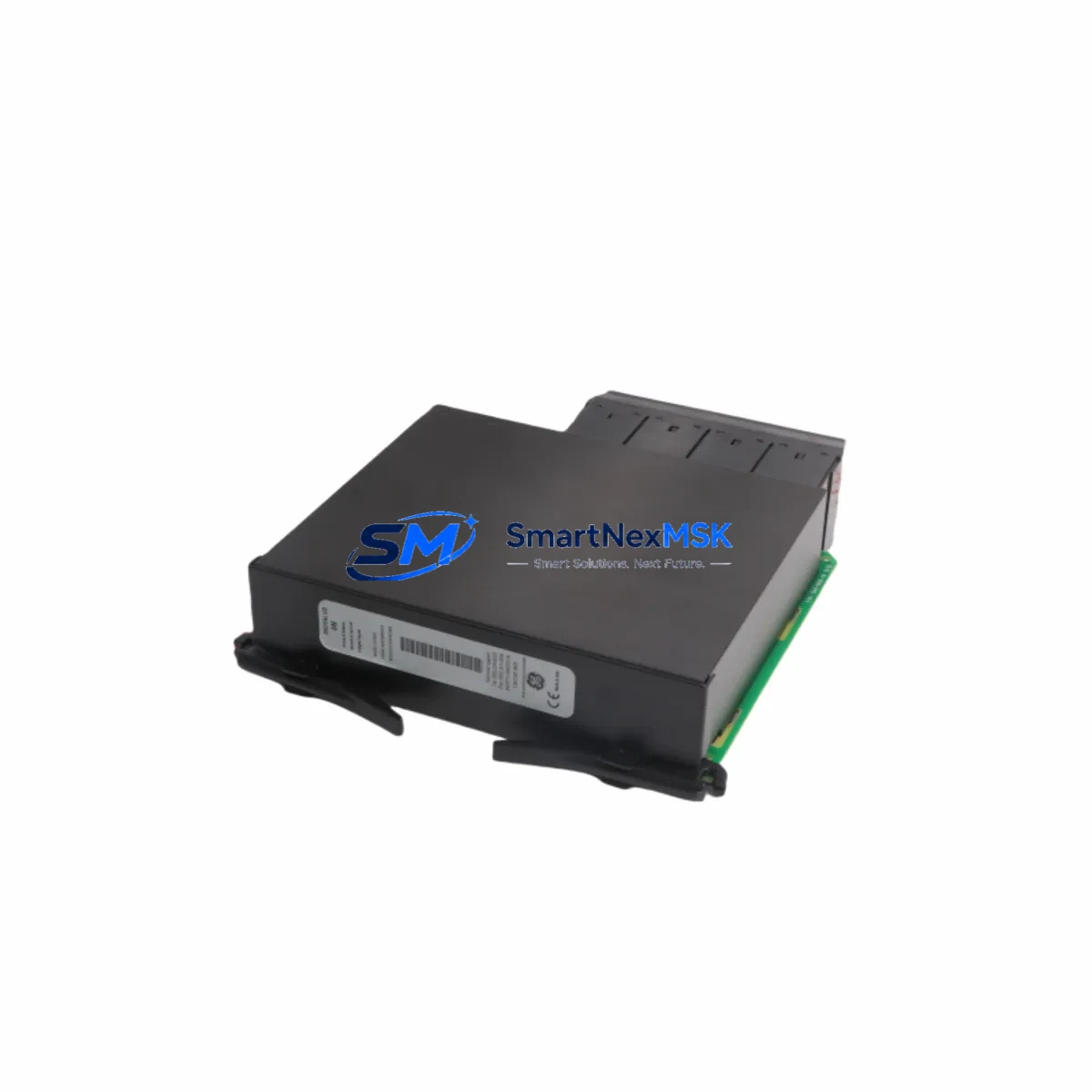
This module slots directly into the UR Series modular chassis, occupying a standard I/O slot and interfacing with the relay’s internal backplane without requiring firmware modification or hardware rework in most configurations. Engineers undertaking a protection relay retrofit or control panel modernization will find the UR6NH a reliable, specification-matched replacement for discontinued or end-of-life digital input assemblies within the UR platform.
Upgrade Compatibility Table
| Parameter | Details |
|---|---|
| Compatible Platform | GE UR Series (UR, URplus chassis) |
| Module Type | Digital Inputs I/O Module |
| Slot Interface | UR Series standard backplane slot |
| Installation Requirement | Direct slot insertion; no hardware modification required in standard configurations |
| Communication Compatibility | Compatible with UR Series internal communication bus; supports IEC 61850, DNP3, and Modbus RTU relay-level protocols via host relay CPU |
| Replacement Recommendation | Suitable as drop-in replacement for equivalent UR Series digital input modules; verify slot position and address assignment before commissioning |
| Commissioning Focus | Module address configuration, input wiring polarity, wet/dry contact settings, and logic mapping in EnerVista UR Setup software |
| Warranty | 12 Months — covers manufacturing defects and functional failure under normal operating conditions |
Retrofit Planning for Existing Automation Systems
Successful integration of the UR6NH into an existing protection relay panel begins well before the module arrives on site. Retrofit engineers should start by auditing the current UR Series chassis configuration — identifying which slots are occupied by digital input modules, analog input modules, digital output modules, and communications modules. In a typical UR Series bay controller or feeder protection relay, the chassis may also house a UR6CT CT/VT input module, a UR6D digital output module, and a UR CPU module running the protection logic. Understanding the full slot map prevents address conflicts and ensures the UR6NH is assigned the correct logical position within the relay’s I/O architecture.
Terminal wiring is a critical step. The UR6NH accepts both wet and dry contact digital inputs, and the field wiring must be verified against the original relay wiring diagrams. In older installations, terminal blocks may be labeled according to legacy UR Series documentation, and engineers should cross-reference the current GE EnerVista UR Setup software configuration to confirm that input assignments match the physical wiring. Where the original relay used a UR6NH or equivalent module in a specific slot, the replacement module must be inserted in the same slot to preserve the logical I/O mapping without requiring a full settings file revision.
Power supply capacity is another consideration. The UR Series chassis power supply — often a UR6PP or equivalent power supply module — must have sufficient headroom to support the UR6NH alongside other installed modules. Before commissioning, verify the total module current draw against the chassis power supply rating. In retrofit scenarios where additional I/O is being added as part of a broader upgrade, it may be necessary to evaluate whether the existing power supply module can support the expanded configuration or whether a higher-capacity replacement is required.
For sites migrating from older SCADA or RTU-based architectures to IEC 61850 substation automation, the UR6NH’s digital inputs feed directly into the UR relay’s GOOSE messaging and data model, enabling seamless integration with modern IEC 61850 station buses and process bus architectures. Engineers should confirm that the host relay’s communications module — such as a UR6ET Ethernet communications module — is configured correctly to publish the digital input states as part of the relay’s logical node model. This is particularly important in projects where the UR Series relay is being integrated with a new substation automation system (SAS) or protection and control IED network.
In motor management and industrial drive protection applications, the UR6NH digital inputs are commonly used to monitor auxiliary contacts from motor control centers (MCCs), circuit breakers, and disconnect switches. During a retrofit, engineers should verify that the input voltage thresholds and contact debounce settings in the relay settings file are appropriate for the field devices being monitored. Where the original relay was connected to a programmable logic controller (PLC) via hardwired I/O, the retrofit plan should include a review of the PLC I/O mapping to ensure that the digital input states reported by the UR6NH are correctly interpreted by the control system.
Downtime Control During System Migration
Minimizing downtime during a protection relay retrofit is a primary concern for plant engineers and utility maintenance teams. The UR6NH’s direct slot compatibility with the UR Series chassis means that in most cases, the module swap can be completed during a planned maintenance window without requiring a full relay replacement or settings file rebuild. The key to a fast, low-risk swap is preparation: the replacement module should be bench-tested and pre-configured before it arrives on site, using a copy of the existing relay settings file loaded into EnerVista UR Setup software.
Before removing the original module, the engineering team should capture a full settings backup from the relay, document the current I/O status, and verify that all protection functions dependent on the digital inputs being replaced are either inhibited or transferred to alternative inputs during the swap window. Where the relay is part of a dual-redundant protection scheme or a main-backup relay arrangement, the backup relay should be confirmed in service before the primary relay is taken out of service for the module replacement.
After installing the UR6NH, the commissioning sequence should include a point-by-point input verification — applying test signals to each digital input terminal and confirming the correct response in the relay’s event log and HMI display. Where the relay is connected to a SCADA system or DCS via DNP3 or IEC 61850, the digital input states should be verified at the master station level to confirm end-to-end signal integrity. The 12-month warranty covering the UR6NH provides additional assurance that any latent manufacturing defects will be addressed without additional cost to the end user.
Retrofit Support FAQ
Q1: Is the GE UR6NH a direct drop-in replacement for the original digital inputs module in my UR Series relay?
In most UR Series chassis configurations, the UR6NH is a direct slot-compatible replacement. However, engineers should verify the slot position, module address assignment, and input wiring configuration against the existing relay settings file before commissioning. Where the original module was configured with specific wet/dry contact settings or input voltage thresholds, these settings should be replicated in the replacement module’s configuration.
Q2: What commissioning steps are required after installing the UR6NH?
After physical installation, the commissioning sequence includes verifying the module address in EnerVista UR Setup, performing a point-by-point input test using a secondary injection test set or field contact simulation, confirming the digital input states in the relay’s event log, and verifying end-to-end signal integrity at the SCADA or DCS master station. Any protection functions dependent on the replaced inputs should be re-enabled and tested before returning the relay to service.
Q3: Can the UR6NH be used in a UR Series relay that has been upgraded to support IEC 61850?
Yes. The UR6NH digital inputs feed into the UR relay’s internal data model and are published as part of the relay’s IEC 61850 logical node structure via the host relay’s communications module. No additional configuration of the UR6NH itself is required for IEC 61850 compatibility — the protocol mapping is handled at the relay CPU and communications module level.
Q4: What does the 12-month warranty cover?
The 12-month warranty covers manufacturing defects and functional failure under normal operating conditions. Each unit undergoes pre-shipment functional testing to verify digital input response, backplane interface integrity, and module identification. Warranty claims are supported by our technical team, and replacement units can be dispatched on an expedited basis to minimize site downtime.
© 2026 SMARTNEXMSK. All rights reserved.
Original Source: https://smartnexmsk.com
Contact: sales@smartnexmsk.com | +86 18259474341