GE UR6PH Retrofit-Ready Digital I/O Module for UR Series Control Systems
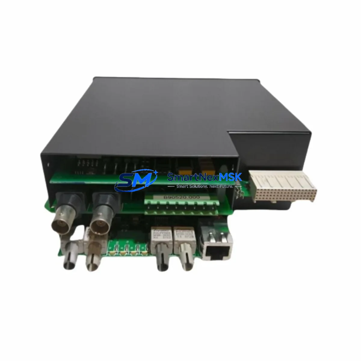
The GE UR6PH is a high-density Digital I/O Module engineered for seamless integration into GE’s Universal Relay (UR) Series protection and control platforms. Designed with retrofit compatibility at its core, the UR6PH serves as a direct replacement for discontinued or aging I/O modules within UR-series relay chassis, enabling power utilities, industrial facilities, and substation engineers to modernize legacy protection systems without full panel replacement. Whether you are upgrading an aging UR 6 Series rack or restoring a failed I/O slot in a live protection scheme, the UR6PH delivers the electrical and logical compatibility required to maintain system continuity with minimal downtime.
The module slots directly into the standard UR-series backplane, maintaining compatibility with the UR chassis communication bus and the relay’s internal logic engine. Engineers migrating from older GE D60, L90, T60, or B30 relay configurations will find the UR6PH’s terminal layout and I/O addressing consistent with established UR platform conventions, reducing the need for extensive program re-mapping or HMI screen redesign. The module supports both wet and dry contact inputs and provides configurable output relay contacts suitable for trip, alarm, and control functions in substation automation environments.
When planning a retrofit around the UR6PH, the first step is verifying the host chassis power budget. The UR-series power supply module — typically a UR 9F or UR 9G power supply card — must have sufficient headroom to support the additional I/O load. Engineers should audit the existing slot assignments across the UR chassis backplane before insertion, confirming that the module address assigned in the relay’s settings file (via EnerVista UR Setup software) does not conflict with other installed modules such as the UR 8D communications card or UR 5A analog I/O module. Terminal wiring should be verified against the original relay wiring diagram, paying particular attention to the polarity of DC input circuits and the contact rating of output relays driving external trip coils or lockout relays.
Upgrade Compatibility Table
| Parameter | Details |
|---|---|
| Compatible Chassis | GE Universal Relay (UR) Series — UR 6, UR 7, UR 8 slot chassis |
| Backplane Interface | UR-series internal communication bus (proprietary backplane) |
| Input Type | Configurable wet/dry contact digital inputs |
| Output Type | Form-A and Form-C output relay contacts |
| Communication Compatibility | IEC 61850 GOOSE, DNP3, Modbus RTU/TCP (via UR 8D comms module) |
| Software Configuration | EnerVista UR Setup (all versions supporting UR 6PH slot type) |
| Replacement Targets | Discontinued UR I/O modules; aging D60, L90, T60, B30 relay I/O slots |
| Installation Requirement | Hot-swap not supported; relay must be de-energized before module insertion |
| Commissioning Tool | EnerVista UR Setup + RS232/USB programming cable |
| Warranty | 12 Months — covers manufacturing defects and functional failure under normal operating conditions |
Retrofit Planning for Existing Automation Systems
A successful UR6PH retrofit begins well before the module arrives on site. The engineering team should extract the current relay settings file using EnerVista UR Setup and document all existing I/O assignments, logic equations, and FlexLogic operands that reference the slot being replaced. If the original module was a UR 5D digital I/O card or a UR 5E contact I/O module, the UR6PH’s expanded I/O count may require re-indexing operand references within the relay’s FlexLogic configuration. This is a controlled process but must be completed and verified in a test environment before field deployment.
For systems where the UR relay communicates upstream to a substation RTU or SCADA system via DNP3 or IEC 61850, the UR 8D communications module must be confirmed as operational and its data map reviewed to ensure that any new I/O points introduced by the UR6PH are correctly mapped to DNP3 binary input/output objects or IEC 61850 logical nodes. In installations using a GE D400 or SEL-3530 RTAC as the station-level gateway, the data model update should be coordinated with the SCADA team to avoid alarm flooding or missed trip signals during the cutover window.
Panel builders and retrofit contractors should also verify the UR chassis backplane ribbon cable condition before inserting the UR6PH. Aged or damaged backplane connectors are a common source of intermittent I/O faults in older UR installations. If the chassis is a first-generation UR 6-slot frame, consider whether a full chassis replacement with a current-production UR 8-slot chassis is more cost-effective than a module-level repair, particularly if multiple slots show signs of wear. Alongside the UR6PH, common companion components in a full retrofit bill of materials include the UR 9G power supply module, UR 8D Ethernet communications card, UR 5A analog input module, and the EnerVista programming cable — all of which may need to be sourced simultaneously to complete the upgrade in a single planned outage window.
Downtime Control During System Migration
Minimizing protection system downtime during a UR6PH module swap requires a structured outage plan. Begin by obtaining a maintenance window from the operations team and confirming that all upstream breakers and protection zones covered by the relay are either transferred to backup protection or placed under a formal protection-out-of-service (POOS) permit. Before de-energizing the relay, capture a full settings backup via EnerVista UR Setup and record all active I/O states from the relay’s front-panel display or via the relay’s web interface if the UR 8D communications module is installed.
During the physical swap, label all terminal wiring before disconnection and photograph the terminal block layout for reference. The UR6PH uses the same terminal block form factor as previous UR I/O modules, so wiring reconnection is straightforward if the original wiring is intact. After insertion, power up the relay and allow the UR6PH to complete its self-test sequence — indicated by the module’s status LED transitioning from amber to green. Load the previously saved settings file and verify that all I/O assignments are correctly recognized by the relay firmware. Perform a functional test of each input and output circuit using a relay test set such as the Omicron CMC 356 or Megger SMRT46 before returning the relay to service. The entire process, when well-planned, can typically be completed within a 4–6 hour outage window, preserving the integrity of the original protection logic and HMI alarm displays without requiring a full relay re-commissioning.
Retrofit Support FAQ
Q1: Is the GE UR6PH a direct drop-in replacement for older UR Series I/O modules?
A: The UR6PH is designed for physical and electrical compatibility with the UR-series chassis backplane. However, firmware version compatibility should be verified using EnerVista UR Setup before installation. In most cases, a settings file update is required to recognize the UR6PH’s I/O point count, but no hardware modifications to the chassis are needed.
Q2: What wiring changes are required when replacing a UR 5D with the UR6PH?
A: Terminal block pinouts are consistent across UR I/O module generations. In most retrofit scenarios, existing field wiring can be reconnected without modification. Engineers should verify input voltage ratings and output contact ratings against the new module’s datasheet to confirm compatibility with existing field devices such as auxiliary relays, annunciators, and trip coils.
Q3: Does the UR6PH support IEC 61850 GOOSE messaging?
A: GOOSE messaging in the UR platform is managed by the UR 8D communications module, not the I/O module directly. The UR6PH’s digital inputs and outputs can be mapped to GOOSE datasets through the relay’s FlexLogic and IEC 61850 configuration in EnerVista UR Setup, provided the UR 8D is installed and the relay firmware supports IEC 61850 Edition 2.
Q4: What does the 12-month warranty cover?
A: The 12-month warranty covers manufacturing defects and functional failures under normal operating conditions from the date of shipment. It includes free replacement or repair of the UR6PH module. Damage caused by incorrect installation, overvoltage, or physical mishandling is excluded. All units undergo pre-shipment functional testing to verify I/O operation, contact continuity, and backplane communication before dispatch.
© 2026 SMARTNEXMSK. All rights reserved.
Original Source: https://smartnexmsk.com
Contact: sales@smartnexmsk.com | +86 18259474341