GE UR7BH Retrofit-Ready Communication Card for UR Series Control Systems
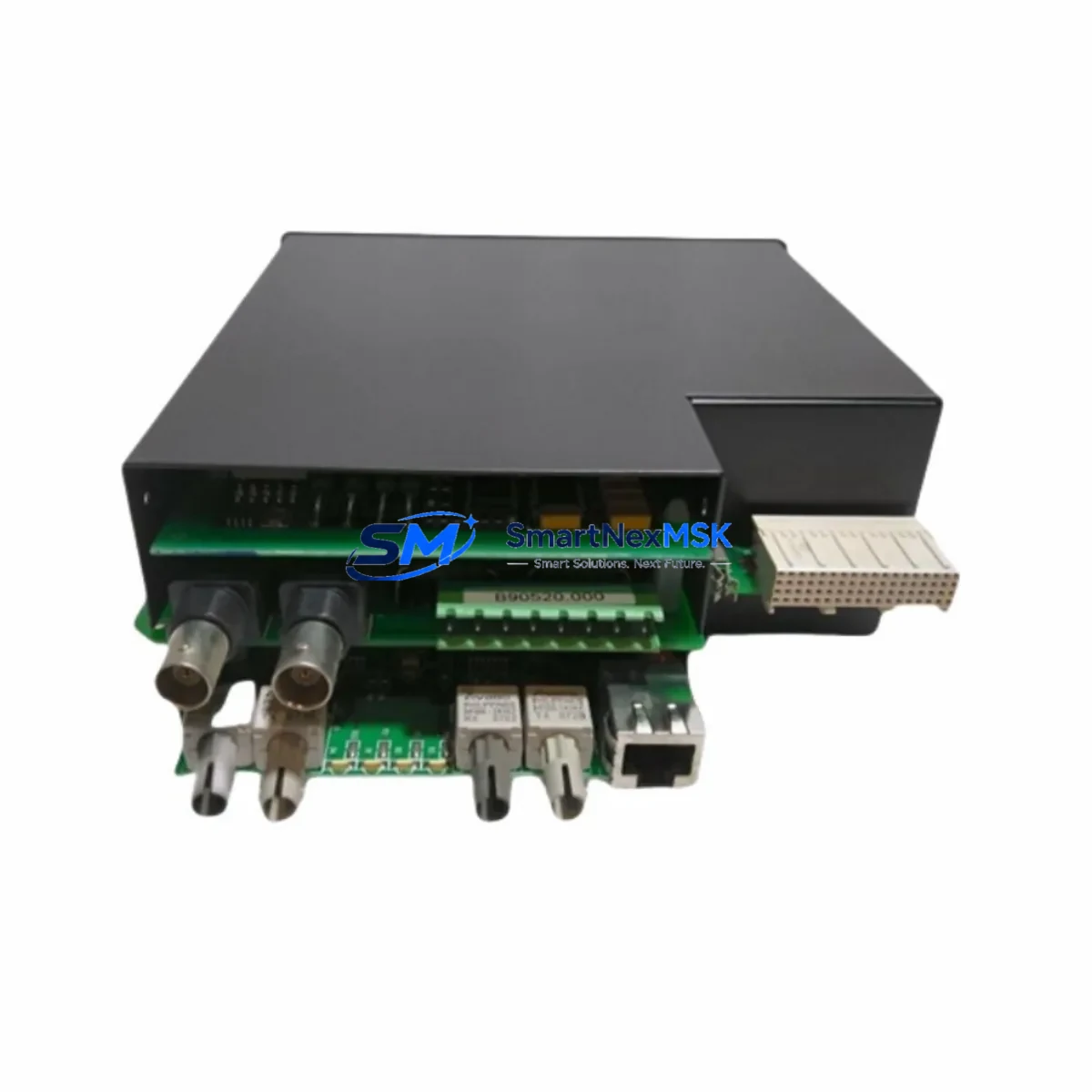
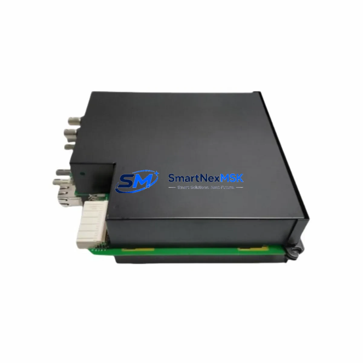
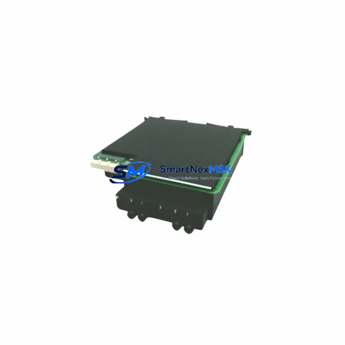
The GE UR7BH is a high-reliability communication interface card engineered for the GE UR Series protection relay platform. Designed to support seamless retrofit and upgrade projects, the UR7BH enables aging substation automation systems to maintain operational continuity while migrating to modern communication architectures. Whether you are replacing a failed card in an active protection relay, upgrading a legacy control cabinet, or expanding I/O and communication capacity across a multi-relay installation, the UR7BH delivers the compatibility, durability, and protocol support that industrial engineers demand.
SMARTNEXMSK maintains verified stock of the UR7BH sourced from authorized supply chains, with each unit subject to pre-shipment functional testing. All units are covered by a 12-month warranty from the date of delivery, providing procurement teams and maintenance engineers with the confidence needed for critical infrastructure projects.
Upgrade Compatibility Table
| Parameter | Details |
|---|---|
| Compatible Platform | GE UR Series (UR, URplus, C30, C60, C70, D60, F35, F60, L90, M60, N60, T35, T60) |
| Card Type | Communication Interface Module |
| Slot Compatibility | UR Series modular backplane communication slot |
| Protocol Support | IEC 61850 GOOSE, DNP3, Modbus RTU/TCP, IEC 60870-5-103/104 |
| Installation Requirement | Hot-swap capable; relay de-energization recommended for safe replacement |
| Terminal / Connector | Rear-panel fiber or copper port per UR7BH variant; verify port type before ordering |
| Replacement Recommendation | Direct drop-in for failed or end-of-life UR Series communication cards |
| Commissioning Note | Firmware version alignment with relay CPU required; verify via EnerVista UR Setup |
| Warranty | 12 months from shipment date |
Retrofit Planning for Existing Automation Systems
Successful retrofit of a UR7BH into an existing UR Series relay installation requires systematic pre-work across several engineering disciplines. Before removing the legacy communication card, engineers should document the existing relay configuration using EnerVista UR Setup software, capturing all protection settings, communication parameters, GOOSE subscriptions, and analog channel assignments. This configuration file serves as the baseline for post-replacement verification.
In multi-relay substations, the UR7BH typically operates alongside other UR Series modules such as the UR6H analog input card, UR8AH digital output module, and UR9H power supply module. When planning a cabinet-level upgrade, it is common to simultaneously replace the UR9H power supply to ensure adequate current capacity for the expanded communication load introduced by modern IEC 61850 GOOSE messaging. Engineers should verify that the existing UR Series backplane — whether a 3-slot, 5-slot, or 8-slot chassis — can accommodate the UR7BH without requiring a full chassis replacement.
Communication protocol migration is a frequent driver for UR7BH upgrades. Many legacy installations rely on Modbus RTU over RS-485 or older DNP3 serial links connected to a SCADA master via a dedicated RTU or protocol converter. Replacing the communication card with a UR7BH supporting IEC 61850 allows the relay to participate directly in a station bus architecture, eliminating the need for intermediate protocol converters and reducing latency in protection signaling. During this migration, the SCADA engineering team must update the data model in the control center to reflect the new IEC 61850 logical node structure exported from the UR7BH’s ICD file.
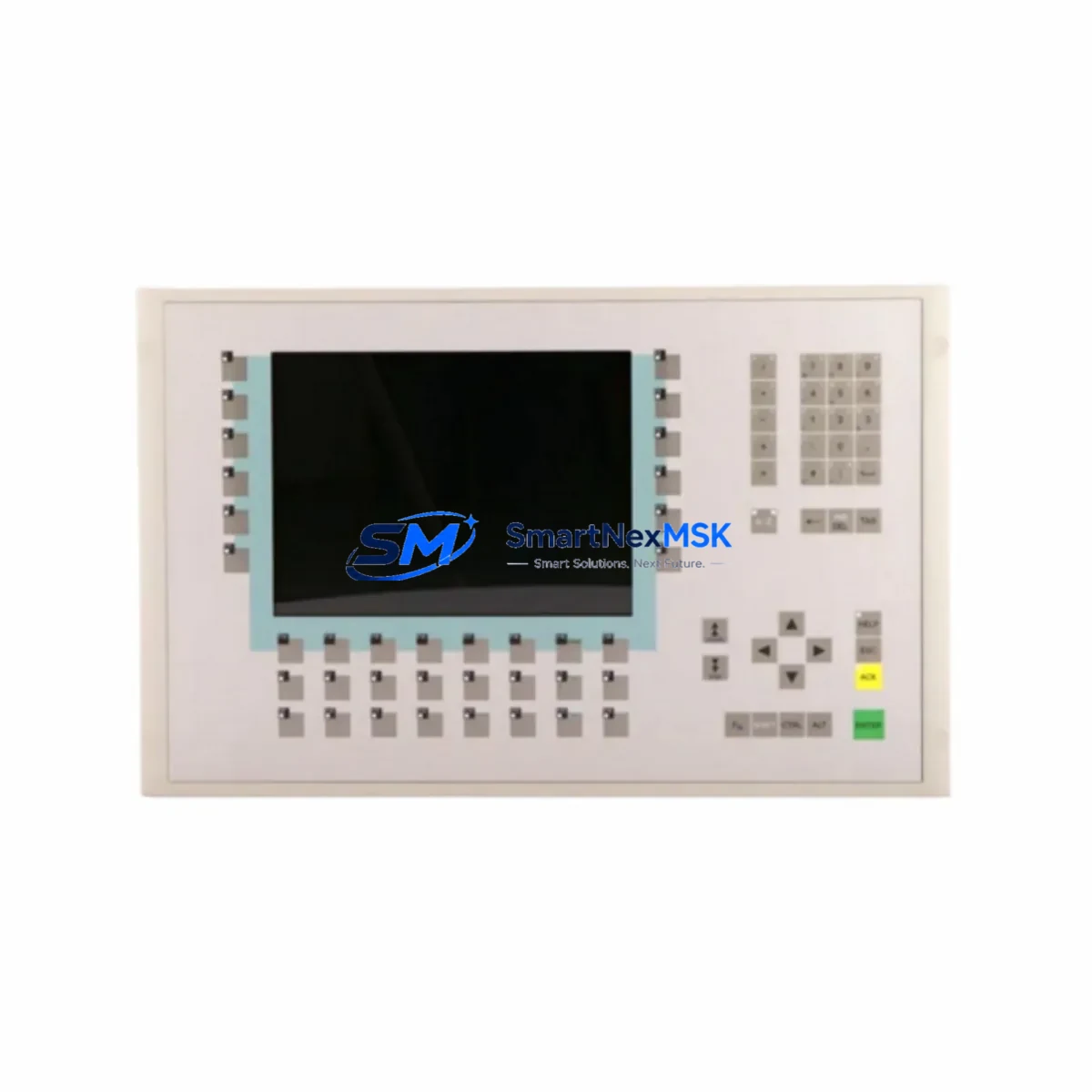
For installations where the UR Series relay interfaces with a GE Multilin SR series or a third-party HMI panel, the UR7BH upgrade may require updating the HMI communication driver and refreshing the HMI screen templates to reflect the new register map or data object references. Coordination with the HMI vendor or the site’s DCS engineering team is recommended before cutover. In some cases, a temporary parallel communication path — maintaining the legacy Modbus link while commissioning the new IEC 61850 connection — can significantly reduce the risk of control interruption during the transition period.
I/O expansion projects that incorporate the UR7BH alongside additional UR6H analog input cards or UR8AH digital I/O modules should also verify that the relay’s CPU module — such as the UR2H or UR3H processor card — has sufficient processing headroom to handle the increased data throughput. Firmware upgrades to the CPU may be required to support the full feature set of the UR7BH, and these should be tested in a staging environment or on a duplicate relay configuration before being applied to the live system.
Downtime Control During System Migration
Minimizing downtime during a UR7BH replacement is achievable with disciplined pre-staging and a structured cutover plan. The recommended approach is to pre-configure the replacement UR7BH offline using EnerVista UR Setup, loading the saved relay configuration file and verifying all communication parameters, IP addresses, GOOSE dataset mappings, and protection group settings before the card is installed in the field. This offline pre-commissioning step can reduce on-site cutover time from several hours to under 30 minutes in most cases.
During the physical replacement, the relay should be taken out of service in coordination with the substation operations team, following the site’s switching and isolation procedures. The original program logic stored in the relay’s non-volatile memory is preserved during a card swap, provided the CPU module and its associated UR2H or UR3H processor card remain undisturbed. After installing the UR7BH, engineers should perform a full communication link test — verifying GOOSE message reception at peer relays, confirming DNP3 or Modbus polling responses at the SCADA master, and checking that all analog and digital I/O channels report correctly through the new communication path.
For critical protection applications where any interruption to the protection scheme is unacceptable, a temporary bypass using a portable protection relay or a hardwired interlock can maintain protection coverage during the card replacement window. SMARTNEXMSK’s technical team can provide pre-shipment configuration assistance and commissioning checklists tailored to your specific UR Series relay model and substation architecture.
Retrofit Support FAQ
Q1: Is the UR7BH a direct replacement for all UR Series communication cards?
The UR7BH is compatible with the modular communication slot of the GE UR Series platform, but the specific port configuration (fiber vs. copper, single-mode vs. multimode) must match the existing installation. Confirm the exact variant suffix of your current card before ordering. SMARTNEXMSK can assist with cross-referencing the original part number to the correct UR7BH variant.
Q2: What firmware version is required on the relay CPU to support the UR7BH?
Firmware compatibility depends on the specific UR Series relay model. In general, UR Series relays running firmware version 7.0x or later fully support the UR7BH’s IEC 61850 feature set. Earlier firmware versions may support the card in Modbus or DNP3 mode only. Firmware upgrade files are available through GE Grid Solutions’ EnerVista portal, and SMARTNEXMSK recommends verifying compatibility before shipment.
Q3: How is the UR7BH tested before shipment?
Each UR7BH unit supplied by SMARTNEXMSK undergoes a pre-shipment functional test that verifies communication port integrity, backplane connector condition, and basic protocol response. Units that fail any test criterion are quarantined and not shipped. A test report is available upon request for critical infrastructure procurement.
Q4: What does the 12-month warranty cover?
The 12-month warranty covers manufacturing defects and functional failures under normal operating conditions. It does not cover damage resulting from incorrect installation, overvoltage events, or physical mishandling. In the event of a warranty claim, SMARTNEXMSK will arrange for a replacement unit to be shipped within 5 business days of claim verification, minimizing the impact on your maintenance schedule.
© 2026 SMARTNEXMSK. All rights reserved.
Original Source: https://smartnexmsk.com
Contact: sales@smartnexmsk.com | +86 18259474341