HITACHI LCE250A Retrofit-Ready Logic Board for LCE Series: Compatible Modernization & Smooth System Upgrade
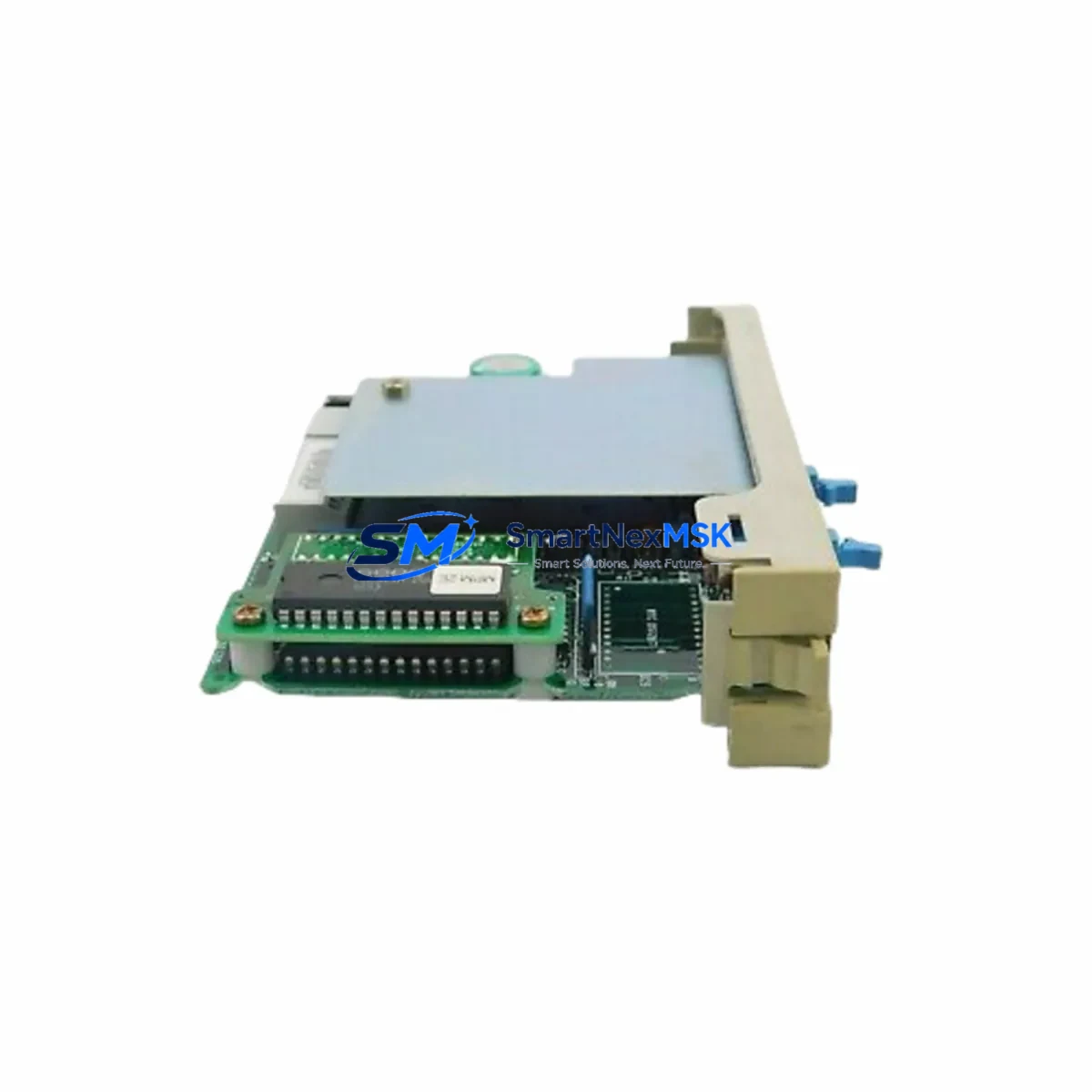
The HITACHI LCE250A is a logic control printed circuit board (PCB) designed for HITACHI LCE Series elevator control systems. As aging LCE-platform installations approach end-of-service life, the LCE250A has become a critical retrofit component for maintenance teams, elevator contractors, and facility managers seeking to extend operational life without a full system overhaul. Whether you are replacing a failed board, upgrading a degraded control cabinet, or migrating from a discontinued predecessor model, the LCE250A provides a wiring-compatible, drop-in upgrade path that minimizes downtime and preserves existing program logic wherever possible.
Our inventory of the HITACHI LCE250A is sourced from verified supply channels, fully tested prior to shipment, and backed by a 12-month warranty. Each unit undergoes functional verification covering power input tolerance, relay output response, serial communication handshake, and I/O signal integrity before leaving our facility. This ensures that the board you receive is ready for immediate installation and commissioning.
Upgrade Compatibility Table
| Parameter | Details |
|---|---|
| Compatible Platform | HITACHI LCE Series elevator control systems |
| Typical Predecessor Models | LCE200A, LCE210A, LCE220A (verify backplane connector pitch before installation) |
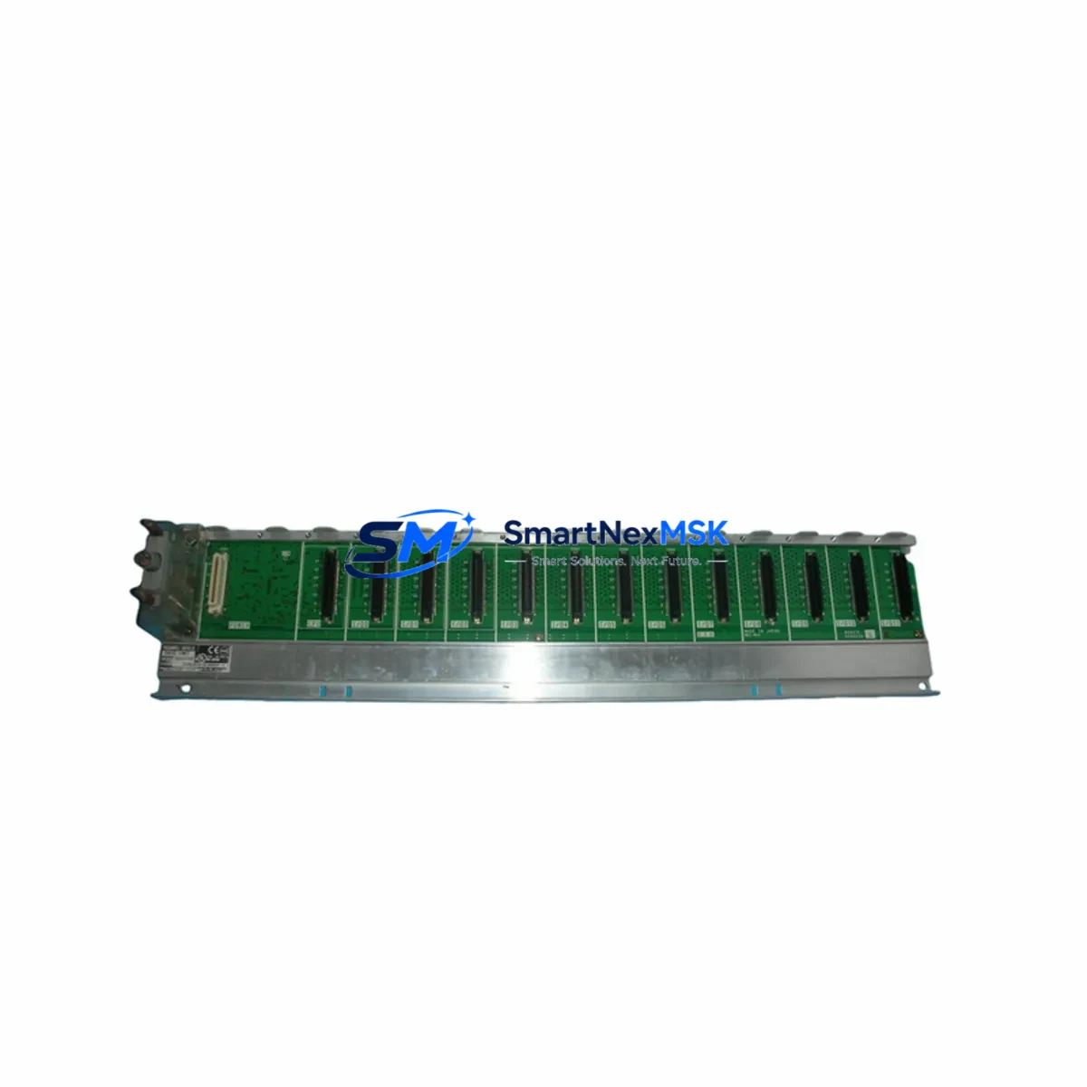
| Backplane Interface | Standard LCE-series edge connector; confirm slot position with cabinet layout drawing |
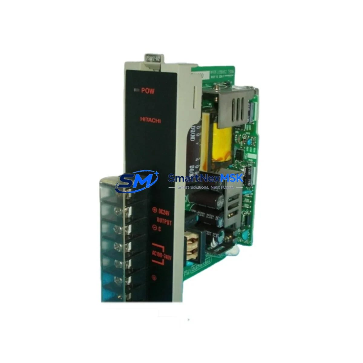
| Power Supply Requirement | DC 24V logic rail; verify HITACHI PS-LCE or equivalent power module output before swap |
| Communication Protocol | RS-485 serial; compatible with HITACHI group controller and CAN-based dispatcher links |
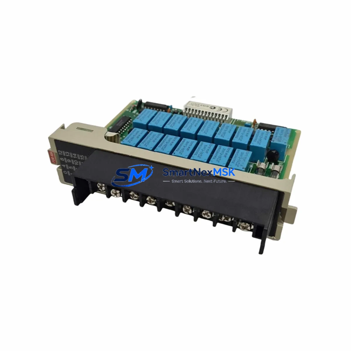
| I/O Compatibility | Compatible with existing LCE-series I/O expansion modules; address DIP switches must be re-verified post-installation |
| HMI / Monitoring | Compatible with HITACHI service tool and standard LCE HMI panels; screen mapping preserved when firmware version matches |
| Installation Method | Direct board swap; no cabinet rewiring required in standard configurations |
| Commissioning Requirement | Parameter re-entry or upload from backup; I/O address confirmation; test run in inspection mode |
| Warranty | 12 months from date of shipment; covers manufacturing defects and functional failure under normal operating conditions |
Retrofit Planning for Existing Automation Systems
Successful LCE250A installation begins well before the board arrives on site. A structured retrofit plan reduces risk, shortens the commissioning window, and protects the integrity of the existing control program. The following workflow reflects best practice for LCE-platform modernization projects.
Step 1 — System Audit: Before ordering, document the existing cabinet configuration. Record the installed power supply module (typically a HITACHI PS-LCE series unit), the backplane or rack model, and the firmware version currently running on the logic board. Photograph all terminal wiring on the existing LCE board, paying particular attention to the safety chain input terminals, door zone signal wiring, and the RS-485 communication port connections that link to the group controller or building management system.
Step 2 — Power Capacity Verification: Confirm that the DC 24V logic rail can support the LCE250A’s current draw alongside any co-installed I/O expansion modules. If the existing HITACHI PS-LCE power module is aged or showing voltage sag under load, replace it concurrently to avoid nuisance faults after the board swap. A failing power supply is a common root cause of premature PCB failure in retrofit scenarios.
Step 3 — Backplane and Rack Inspection: Inspect the LCE-series rack or backplane for oxidized connector pins, cracked PCB traces, or mechanical damage. The LCE250A uses the standard LCE edge connector, but connector condition directly affects signal integrity. Clean or replace the backplane connector strip if contact resistance is elevated. If the rack itself is a legacy LCE-R series unit, verify that the slot assignment for the logic board has not been altered by previous field modifications.
Step 4 — Program Backup: If the existing LCE board is still partially functional, use the HITACHI service laptop tool to upload and save the current parameter set, floor table, and door timing data. Store this backup on a dedicated USB drive before removing the old board. This backup is essential for restoring elevator behavior after the swap and eliminates the need to re-enter all parameters from scratch.
Step 5 — I/O Module Address Verification: After installing the LCE250A, verify the DIP switch address settings on all connected I/O expansion modules. Address conflicts between the new logic board and existing I/O modules are a frequent source of commissioning delays. Cross-reference the address map against the original cabinet wiring diagram. If the original diagram is unavailable, use the HITACHI service tool to scan the RS-485 bus and enumerate connected devices.
Step 6 — Communication Link Restoration: Re-establish the RS-485 serial link to the group controller or dispatcher. If the building uses a CAN-based group control network, confirm that the LCE250A firmware supports the installed protocol version. In multi-car installations, verify that the car address assigned to this controller does not conflict with adjacent cars on the same network segment. Communication modules such as the HITACHI CM-LCE or equivalent gateway boards should be re-initialized after the logic board swap.
Step 7 — HMI and Monitoring Panel Reconnection: Reconnect the HMI panel or service display. If the installation uses a HITACHI LCE-series service panel or a third-party monitoring terminal, confirm that the display firmware version is compatible with the LCE250A. In most standard configurations, the HMI screen mapping is preserved automatically when the firmware version on the new board matches the previous installation. If a firmware update is required, perform it before entering the parameter set.
Step 8 — Terminal Wiring Inspection: Before powering up, perform a point-to-point continuity check on all terminal connections reinstated after the board swap. Pay particular attention to the safety chain input, the door operator control outputs, the leveling sensor inputs, and the brake control relay outputs. Incorrect wiring at any of these terminals can cause immediate fault codes or, in worst cases, unsafe elevator behavior during the test run.
Downtime Control During System Migration
Minimizing elevator downtime during a logic board replacement is a primary concern for facility managers and maintenance contractors. A well-prepared LCE250A swap can typically be completed within a single maintenance window of four to eight hours, depending on cabinet condition and the availability of a parameter backup.
The most effective downtime reduction strategy is pre-staging. Receive and inspect the LCE250A before the scheduled maintenance window. Verify the board visually for shipping damage, confirm the firmware version label, and bench-test the unit if a test fixture is available. Having the replacement board on hand and verified eliminates the risk of discovering a defective unit after the old board has already been removed.
Prepare a printed copy of the parameter set and floor table before beginning work. Even if a digital backup exists, a printed reference allows two technicians to work simultaneously — one entering parameters while the other handles wiring verification — cutting the commissioning phase significantly. If the elevator serves a critical facility such as a hospital or data center, coordinate with building management to schedule the outage during the lowest-traffic period and arrange for temporary stair access or alternative vertical transport.
During the swap itself, label every wire before disconnecting it from the old board. Use numbered cable ties or adhesive labels rather than relying on memory or photographs alone. This discipline is especially important on older LCE cabinets where wire colors may have faded or where previous field modifications have introduced non-standard wiring. After reinstalling the LCE250A and reconnecting all terminals, perform a full inspection-mode test run before returning the elevator to normal service. Verify floor leveling accuracy, door timing, safety chain continuity, and group communication response before signing off.
Our team provides pre-shipment functional testing on every LCE250A unit, and our technical support line is available to assist with commissioning questions during your maintenance window. All units ship with a 12-month warranty covering manufacturing defects and functional failure under normal operating conditions.
Retrofit Support FAQ
Q1: Is the HITACHI LCE250A a direct drop-in replacement for the LCE200A or LCE220A?
In most standard LCE-series cabinet configurations, the LCE250A is mechanically and electrically compatible with earlier LCE-series logic boards including the LCE200A and LCE220A. However, you should verify the backplane connector pitch, the firmware version compatibility with your installed I/O modules, and the parameter set structure before committing to the swap. If your cabinet has been field-modified, a wiring diagram review is recommended prior to installation.
Q2: What commissioning steps are required after installing the LCE250A?
After physical installation, you will need to restore the parameter set (either from a backup or by re-entering values manually), verify I/O module address assignments via DIP switch, re-establish the RS-485 communication link to the group controller, confirm HMI panel compatibility, and perform a full inspection-mode test run covering floor leveling, door operation, safety chain, and brake control. Our technical team can provide commissioning guidance specific to your cabinet configuration.
Q3: How do I verify wiring compatibility before removing the old board?
Before disconnecting the existing logic board, photograph all terminal blocks and label every wire with its terminal designation. Cross-reference against the HITACHI LCE-series wiring diagram for your cabinet model. Pay particular attention to the safety chain input terminals, door zone sensor wiring, and the RS-485 port. If the original wiring diagram is unavailable, our team can assist in identifying terminal functions based on your cabinet model and serial number.
Q4: What does the 12-month warranty cover, and what is the return process?
The 12-month warranty covers manufacturing defects and functional failure under normal elevator operating conditions. It does not cover damage resulting from incorrect installation, overvoltage events, or physical mishandling. If a warranty claim is required, contact our sales team with your order number and a description of the fault. We will arrange for inspection and, where the fault is confirmed as a manufacturing defect, provide a replacement unit or repair at no charge.
© 2026 SMARTNEXMSK. All rights reserved.
Original Source: https://smartnexmsk.com
Contact: sales@smartnexmsk.com | +86 18259474341