HITACHI ZSHH661I 43049761 Spare for PSM2 Automation: Reliable DCS Power Supply Replacement for Industrial Uptime
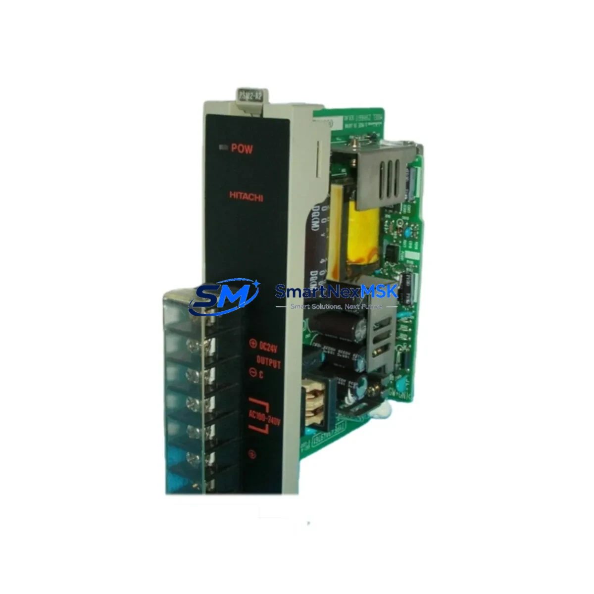
The HITACHI ZSHH661I (Part No. 43049761, Model PSM2-A2) is an original DCS power supply module engineered for continuous-duty industrial control environments. Designed as a core power conditioning and distribution component within HITACHI’s PSM2 series distributed control architecture, this module delivers regulated DC output to field I/O racks, communication backplanes, and processor cards. For maintenance engineers managing aging HITACHI DCS installations, securing a verified spare of the ZSHH661I is a critical step in any downtime-reduction strategy. Our stock is sourced from authorized channels, individually tested prior to dispatch, and covered by a 12-month replacement warranty.
Whether you are executing a planned turnaround, responding to an unscheduled trip, or building a strategic spare parts buffer for a long-running PSM2 system, the ZSHH661I 43049761 PSM2-A2 is a direct, plug-compatible replacement that eliminates the need for firmware reconfiguration or hardware adaptation.
Spare Maintenance Table
| Parameter | Specification / Detail |
|---|---|
| Manufacturer | HITACHI |
| Part Number / SKU | ZSHH661I / 43049761 |
| Model | PSM2-A2 |
| Series | PSM2 (HITACHI DCS) |
| Module Type | DCS Power Supply Module |
| Output Voltage | 24 VDC regulated (nominal) |
| Input Voltage Range | 100–240 VAC, 50/60 Hz (universal input) |
| Mounting | DIN rail / rack-mount backplane, PSM2 series chassis |
| Compatibility | HITACHI PSM2 series DCS racks; compatible with PSM2-A1, PSM2-B series backplanes |
| Operating Temperature | 0°C to +55°C |
| Humidity | 5–95% RH, non-condensing |
| Protection Class | IP20 (panel-mount installation) |
| Weight | Approx. 1,250 g |
| Origin | Japan |
| Condition | Original, new or refurbished-to-spec; pre-shipment tested |
| Warranty | 12 Months — replacement or full refund |
| Lead Time | Ships within 3–5 business days; express available |
| Maintenance Interval | Inspect every 12 months; replace capacitors at 5-year intervals |
Maintenance Planning for Continuous Operation
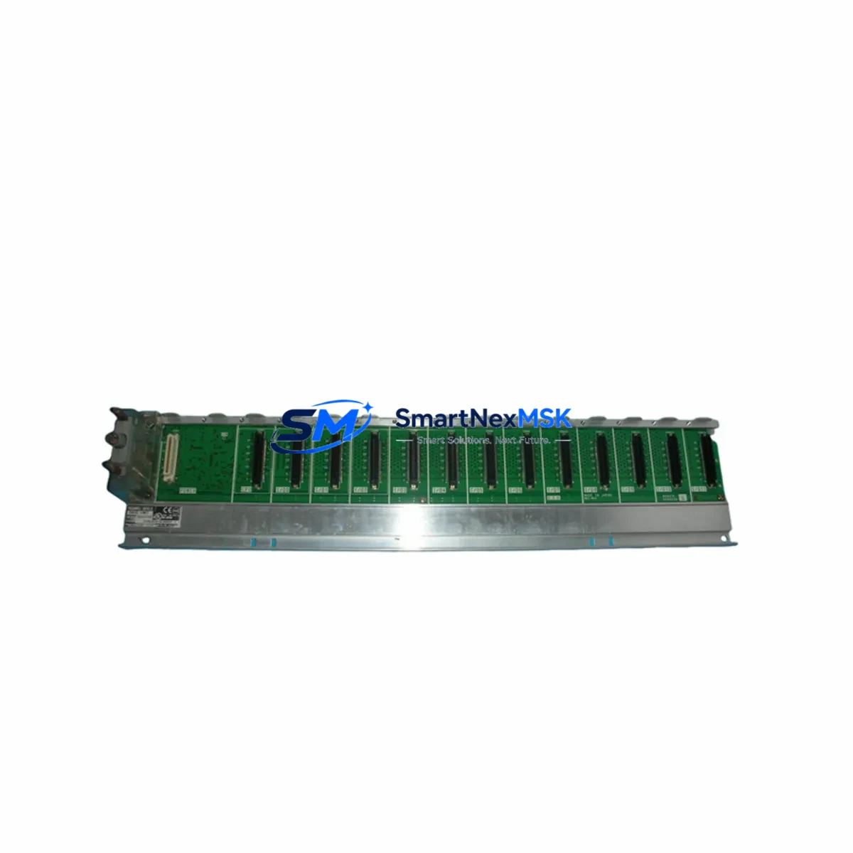
A power supply failure in a DCS rack is rarely an isolated event. When the ZSHH661I PSM2-A2 is flagged for replacement during a control cabinet inspection or after a nuisance trip, experienced maintenance engineers treat it as a trigger for a broader system health review. The power supply module feeds regulated voltage to every card in the PSM2 rack — including the CPU processor module, analog I/O cards, digital I/O modules, and the communication interface card connecting the DCS to field instruments via HART or FOUNDATION Fieldbus.
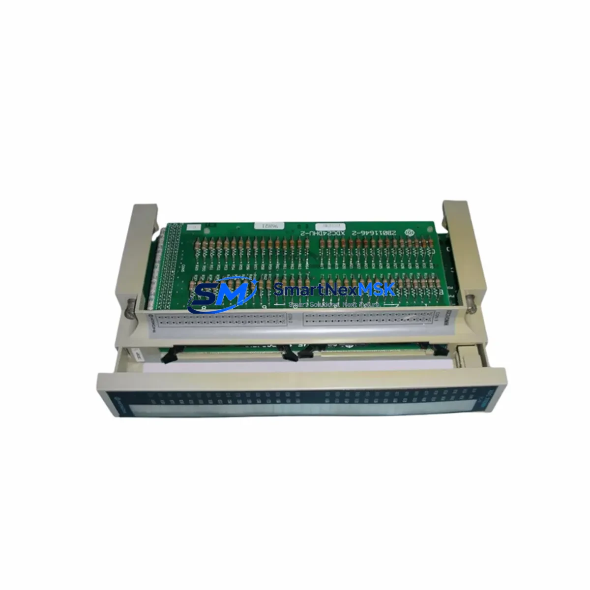
During the same maintenance window, it is best practice to inspect the rack’s terminal blocks and field wiring connectors for signs of oxidation or loose terminations, as voltage fluctuations from a degrading PSM2-A2 can cause intermittent signal errors on 4–20 mA analog input channels. The 24 VDC bus also powers any signal isolators or loop-powered transmitter barriers installed in the marshalling cabinet — these should be verified for correct output after the power module swap.
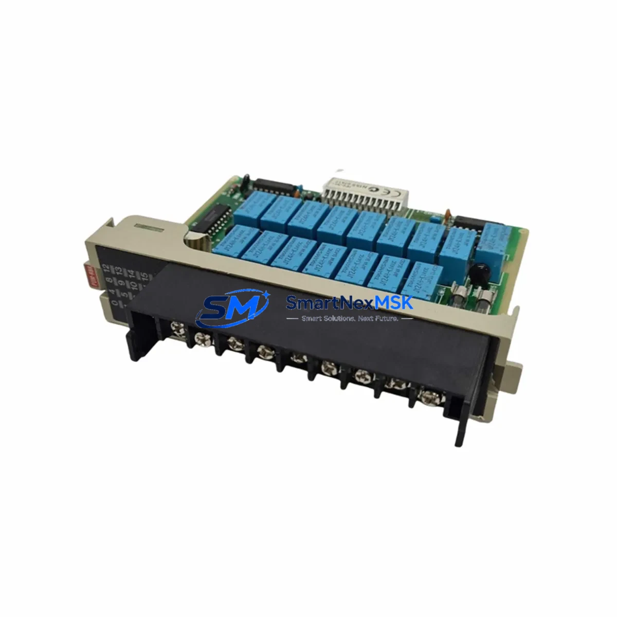
If the PSM2 system includes a redundant power supply configuration, the standby PSM2-A2 module should be tested for automatic switchover capability before the primary unit is removed. Relay output modules and digital output cards in the same rack should be checked for contact wear, particularly if the power interruption caused unexpected coil cycling. The system’s 24 VDC fuse blocks and miniature circuit breakers protecting individual field loops should also be inspected and replaced if any show signs of thermal stress.
For sites running HITACHI’s HISEC or HISEC-E operator stations, the HMI communication link to the DCS controller should be verified after power restoration to confirm that no tag alarms or communication faults were latched during the outage. Where the PSM2 rack interfaces with a PROFIBUS DP or Modbus RTU network, the communication module’s LED diagnostics should be checked to confirm clean bus re-initialization. Keeping a spare ZSHH661I 43049761 alongside a matched set of I/O fuse holders, a spare CPU battery module, and a set of pre-terminated field connector plugs ensures that any future power-related incident can be resolved within a single shift.
Site Replacement Workflow
Step 1 — Isolation and Permit: Obtain a Permit to Work and isolate the affected PSM2 rack from the field power distribution panel. Confirm zero-energy state with a calibrated voltage tester before opening the cabinet door.
Step 2 — Document Current Configuration: Photograph the existing ZSHH661I module label, wiring harness routing, and any DIP switch or jumper settings. Record the rack slot position. This documentation is essential if the replacement module requires any hardware configuration to match the outgoing unit.
Step 3 — Module Extraction: Release the module locking lever and slide the ZSHH661I 43049761 PSM2-A2 out of the backplane connector. Inspect the backplane connector pins for damage or contamination before inserting the replacement.
Step 4 — Install Replacement: Seat the new ZSHH661I firmly into the rack slot until the locking lever engages. Reconnect the AC input wiring to the terminal block, observing correct L/N/PE polarity. Verify that all field connector plugs are fully seated.
Step 5 — Power-Up and Verification: Restore AC supply and observe the module’s status LEDs. Confirm that the 24 VDC output bus reaches nominal voltage within the specified startup time. Check the DCS operator station for any residual alarms and perform a loop check on critical analog inputs before returning the system to automatic control.
Step 6 — Record and Close: Update the maintenance management system (CMMS) with the replacement date, new module serial number, and any observations. Return the removed module for evaluation or disposal per site procedures.
Spare Parts Support FAQ
Q1: Is the HITACHI ZSHH661I 43049761 PSM2-A2 a direct replacement for older PSM2-A1 units?
The PSM2-A2 is the current production revision of the PSM2 power supply family and is backward-compatible with PSM2-A1 rack positions in most configurations. We recommend confirming the backplane connector type and any DIP switch settings against your system documentation before installation. Our technical team can assist with compatibility verification prior to shipment.
Q2: What pre-shipment testing is performed on each ZSHH661I module?
Every unit undergoes a full functional test including input voltage range verification, output voltage regulation under load, ripple measurement, and overcurrent protection trip testing. A test report is available upon request. Modules are packed in anti-static ESD bags with foam cushioning to prevent transit damage.
Q3: How should the ZSHH661I be stored as a long-term spare?
Store in a dry, temperature-controlled environment between 0°C and +40°C, away from direct sunlight and corrosive atmospheres. Keep in the original ESD packaging. For spares held longer than 24 months, we recommend a bench power-up test before deployment to verify capacitor health and output stability.
Q4: What is covered under the 12-month warranty?
The 12-month warranty covers all manufacturing defects and functional failures under normal operating conditions. It includes free replacement or full refund at the buyer’s option. The warranty does not cover damage caused by incorrect installation, overvoltage events, or physical mishandling. Warranty claims are processed within 5 business days of receiving the returned unit.
© 2026 SMARTNEXMSK. All rights reserved.
Original Source: https://smartnexmsk.com
Contact: sales@smartnexmsk.com | +86 18259474341