Hitachi POM-RBH 33029692-1 Maintenance-Ready Spare for POM DCS
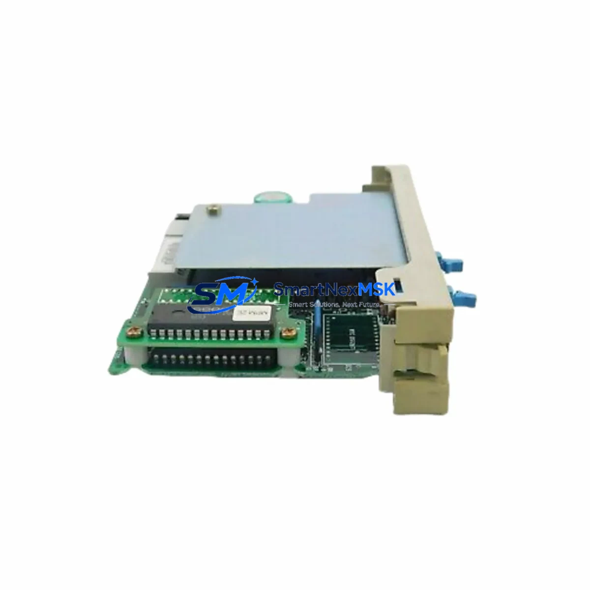
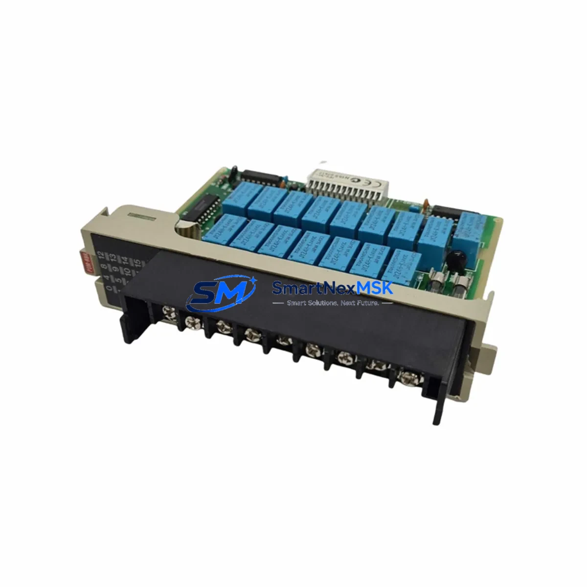
The Hitachi POM-RBH 33029692-1 is an original relay output board designed for HITACHI POM-series Distributed Control Systems (DCS). In industrial automation environments where uptime is non-negotiable, maintaining a verified spare of this board is a frontline strategy against unplanned downtime. Whether you are managing a petrochemical plant, a power generation facility, or a large-scale process manufacturing line, the POM-RBH relay output board sits at the heart of your control cabinet’s output execution layer — translating DCS logic into physical switching actions across field devices, actuators, and interlock circuits.
Sourced directly from authorized supply chains and verified against HITACHI’s original part number 33029692-1, this board is tested before shipment and backed by a 12-month warranty. It is a direct replacement for aging or failed units in HITACHI EX-series and POM-series DCS architectures, ensuring full compatibility without requiring firmware reconfiguration or hardware adaptation.
Spare Maintenance Table
| Parameter | Specification |
|---|---|
| Part Number | POM-RBH / 33029692-1 |
| Brand | HITACHI |
| Series | HITACHI POM / EX DCS Series |
| Module Type | Relay Output Board |
| Output Type | Relay contact output (dry contact) |
| Compatibility | HITACHI EX Series DCS, POM Series Controllers |
| Mounting | Backplane / rack-mount, DCS cabinet installation |
| Operating Temperature | 0°C to 55°C (standard industrial range) |
| Origin | Japan |
| Condition | Original, new or refurbished-tested |
| Pre-shipment Testing | Yes — functional output verification |
| Warranty | 12 Months |
| Lead Time | In stock — ships within 3–5 business days |
| Application | Process control, interlock output, actuator switching |
| Maintenance Recommendation | Inspect relay contacts annually; replace at first sign of contact wear or output drift |
Maintenance Planning for Continuous Operation
When a relay output board such as the POM-RBH 33029692-1 is flagged during a control cabinet inspection or routine point check, experienced maintenance engineers know that the fault rarely exists in isolation. A failed relay output board typically signals stress across the broader output execution chain. Before returning the system to service after replacing the POM-RBH, a thorough inspection of the following associated components is strongly recommended:
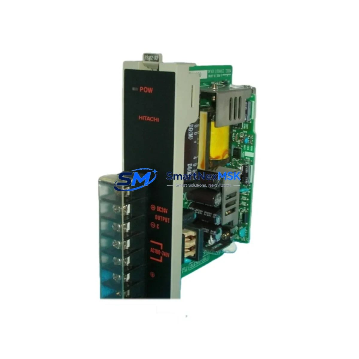
- POM-series Power Supply Module (e.g., POM-PSU) — Verify output voltage stability. An unstable 24 VDC rail is a leading cause of relay board degradation and premature contact failure.
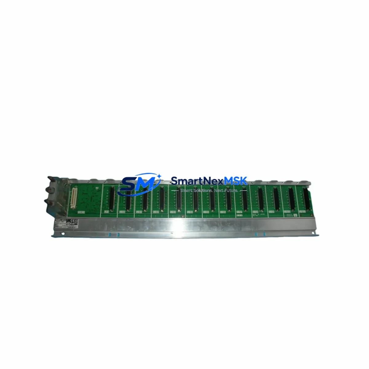
- DCS Backplane / Rack Assembly — Inspect the backplane connector pins for oxidation, mechanical damage, or intermittent contact. A faulty backplane can cause repeated relay board failures even after replacement.
- POM Digital Input Module (POM-DI) — Cross-check input signal integrity. If the relay output was responding to erroneous input signals, the DI module may also require inspection or replacement.
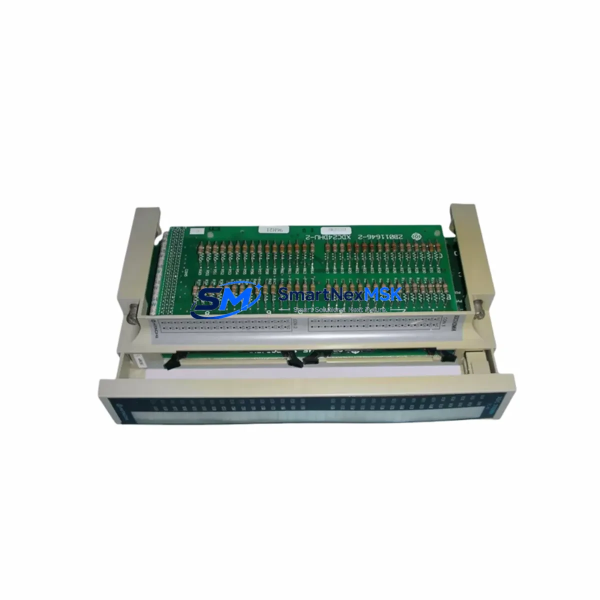
- Field Terminal Blocks and Wiring — Inspect all output-side terminal blocks for loose connections, corrosion, or overheating marks. Terminal block failures can cause relay contact arcing and accelerated wear.
- Interposing Relay Units — Where the POM-RBH drives interposing relays for high-current field devices, inspect the interposing relay coils and contacts for wear. Replace any units showing contact resistance above specification.
- Fuse and Circuit Protection — Verify all output circuit fuses and miniature circuit breakers (MCBs) protecting the relay output loops. A blown fuse on an output channel is often the first visible symptom of a relay board fault.
- Communication Module (e.g., POM-COM or equivalent) — Confirm that the DCS communication link between the controller and the I/O rack is stable. Communication errors can cause false output commands that stress relay contacts.
- Signal Isolators on Critical Output Loops — For loops driving sensitive field instruments, verify that signal isolators are functioning correctly. Isolation failures can introduce ground loops that damage relay output boards.
- HMI / Operator Station Alarm Logs — Review the HMI alarm history for output fault codes, relay failure alarms, or communication timeout events that may have preceded the board failure. This data is essential for root cause analysis.
- Analog Output Module (POM-AO) — If the control loop includes both relay and analog outputs, inspect the analog output module for drift or calibration errors that may have contributed to abnormal relay switching cycles.
Maintaining a structured spare parts inventory that includes the POM-RBH 33029692-1 alongside these associated modules ensures that your maintenance team can execute a complete cabinet restoration within a single planned maintenance window, minimizing the risk of secondary failures after the primary repair.
Site Replacement Workflow
Replacing the Hitachi POM-RBH 33029692-1 in the field is a structured process that, when executed correctly, can restore full DCS output functionality within a single shift. The following workflow is recommended for maintenance engineers performing an in-situ replacement:
- Pre-replacement verification: Confirm the fault is isolated to the POM-RBH board using the DCS diagnostic interface. Check for relay output fault codes on the HMI and verify that the backplane and power supply are functioning normally before proceeding.
- System isolation: Place the affected control loop in manual mode at the DCS operator station. Notify field operators of the planned output interruption. Isolate the output circuit at the field terminal block to prevent unintended actuator movement during the replacement.
- Board removal: Power down the affected I/O rack slot if hot-swap is not supported. Carefully extract the POM-RBH board from the backplane, noting the slot address for re-insertion of the replacement unit.
- Replacement installation: Insert the new POM-RBH 33029692-1 into the correct backplane slot. Ensure the board is fully seated and the locking mechanism is engaged. Restore rack power and verify that the DCS recognizes the new board without configuration errors.
- Functional test: From the DCS engineering station, perform a forced output test on each relay channel. Verify field-side continuity at the terminal block. Confirm that all interlock and control outputs respond correctly before returning the loop to automatic mode.
- Documentation: Record the replacement in the maintenance log, including the date, slot address, old board serial number, and post-replacement test results. Update the spare parts inventory to reflect the consumed unit and initiate a replenishment order.
This replacement workflow is compatible with both planned maintenance shutdowns and emergency corrective maintenance scenarios. The POM-RBH 33029692-1’s direct form-fit-function compatibility with the original HITACHI DCS architecture eliminates the need for software reconfiguration, significantly reducing the time from fault detection to system restoration.
Spare Parts Support FAQ
Q1: Is the POM-RBH 33029692-1 compatible with all HITACHI EX-series DCS configurations?
The POM-RBH 33029692-1 is designed for HITACHI POM-series and EX-series DCS architectures. Compatibility is confirmed by matching the part number and backplane slot type. For legacy system configurations or non-standard rack assemblies, please provide your system model and rack configuration to our technical team at sales@smartnexmsk.com for pre-purchase compatibility verification.
Q2: What pre-shipment testing is performed on the POM-RBH 33029692-1?
Every unit undergoes functional relay output verification prior to shipment. This includes contact continuity testing on all output channels, insulation resistance checks, and visual inspection for physical damage. A test report is available upon request. All units are shipped with protective packaging to prevent transit damage.
Q3: How should the POM-RBH 33029692-1 be stored as a long-term spare?
For long-term spare storage, the board should be kept in its original anti-static packaging in a climate-controlled environment with temperature between 10°C and 40°C and relative humidity below 75% (non-condensing). Avoid storage near strong magnetic fields or corrosive atmospheres. Inspect stored units annually for any signs of component degradation. Boards stored under recommended conditions maintain full functionality for a minimum of 5 years.
Q4: What does the 12-month warranty cover?
The 12-month warranty covers manufacturing defects, component failures under normal operating conditions, and any functional faults identified during the warranty period. Warranty claims require the original purchase documentation and a fault description. Units damaged by incorrect installation, overvoltage, or environmental conditions outside the specified operating range are not covered. Warranty support is provided directly by SMARTNEXMSK — contact sales@smartnexmsk.com or +86 18259474341 for claims processing.
© 2026 SMARTNEXMSK. All rights reserved.
Original Source: https://smartnexmsk.com
Contact: sales@smartnexmsk.com | +86 18259474341