HITACHI LYD105A Retrofit-Ready Digital Input Module for EH Series Control Systems
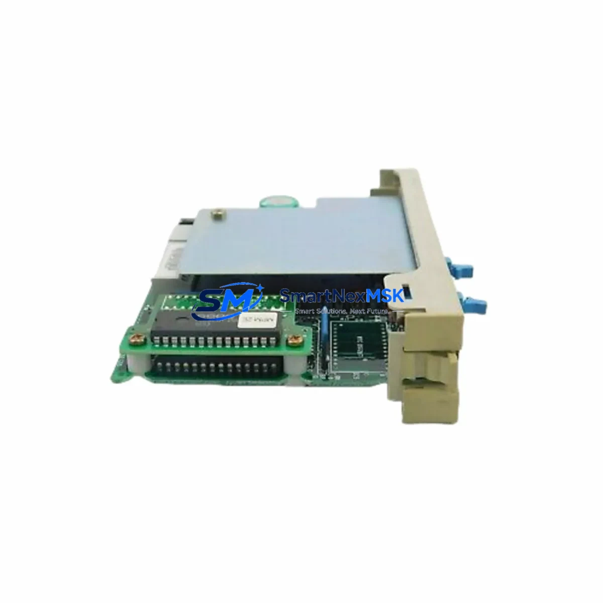
The HITACHI LYD105A is a retrofit-ready digital input module engineered for seamless integration into HITACHI EH Series programmable logic controller platforms. As legacy EH Series control systems approach end-of-life and original spare parts become increasingly scarce, the LYD105A serves as a verified drop-in replacement that preserves existing wiring infrastructure, backplane slot assignments, and ladder logic programs without requiring a full system redesign. Whether you are managing a planned upgrade cycle or responding to an unplanned module failure on the production floor, the LYD105A delivers the electrical and functional compatibility needed to restore control continuity with minimal downtime.
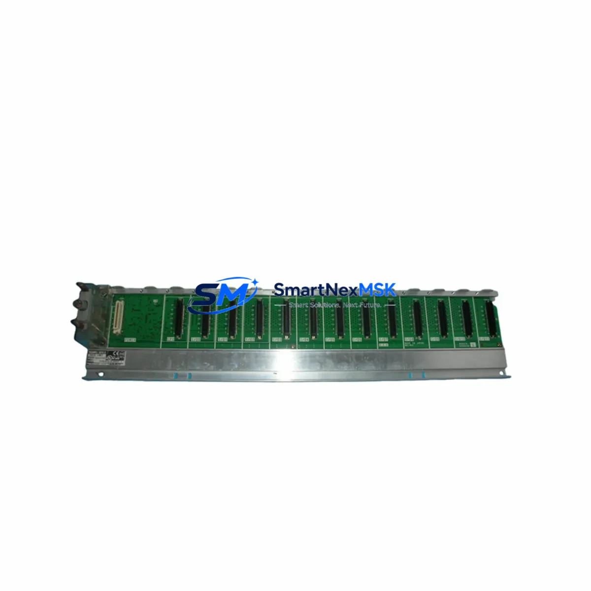
Industrial facilities running HITACHI EH Series controllers — including EH-150, EH-300, and EH-CPU series configurations — frequently encounter challenges sourcing original I/O modules as the product line matures. The LYD105A addresses this directly by maintaining pin-compatible terminal block layouts, identical backplane communication protocols, and equivalent input signal specifications. Engineers responsible for control cabinet upgrades can install the LYD105A into the existing rack without modifying the EH-BSU backplane or reconfiguring the EH-CPU module addressing scheme. This compatibility extends to the associated EH-RM remote I/O expansion units commonly deployed in distributed control architectures.
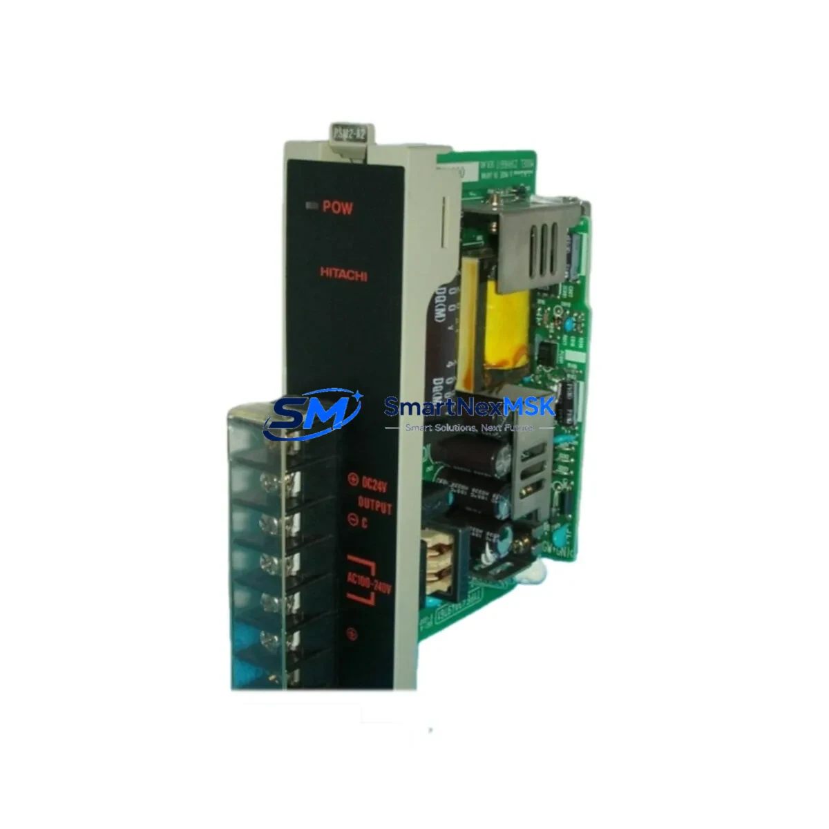
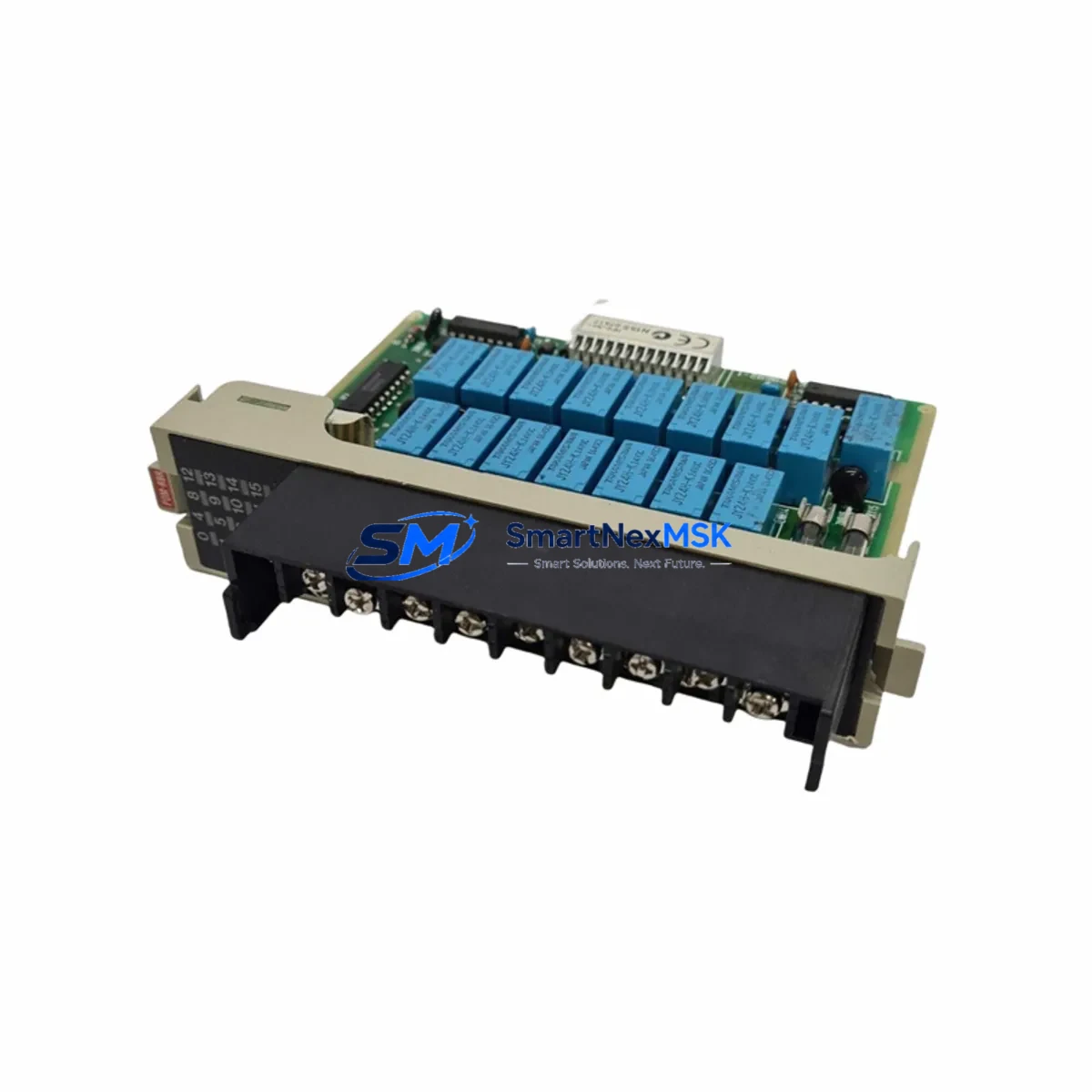
Before committing to a retrofit installation, engineering teams should verify several critical parameters. First, confirm that the control cabinet power supply — typically an EH-PS24 or equivalent 24 VDC regulated supply — provides sufficient current headroom to support the LYD105A alongside existing output modules such as the LYD205A relay output or LYD305A transistor output units. Second, review the terminal wiring diagram against the original module’s I/O map to confirm that field sensor commons, shielding connections, and surge suppression components remain correctly positioned. Third, validate the module address setting using the EH-CPU’s I/O configuration table within the LADDER EDITOR or H-series programming software to ensure the replacement module occupies the correct logical address without conflicting with adjacent modules on the same rack.
Program compatibility is a key concern during any EH Series retrofit. The LYD105A retains the same input bit-mapping structure as the original module, meaning existing ladder rungs referencing input coils X000–X00F (or equivalent addressing depending on slot position) will continue to execute correctly after the swap. No program download or memory initialization is required in most standard replacement scenarios. However, if the retrofit is part of a broader migration from an older EH-150 rack to a newer EH-300 chassis, engineers should audit any slot-dependent addressing offsets and update the HMI screen tag bindings accordingly — particularly where HITACHI’s H-series HMI panels or third-party SCADA systems reference specific I/O addresses via Modbus RTU or HITACHI’s proprietary H-Link communication protocol.
Communication link integrity is another area requiring attention during system migration. The EH Series typically uses H-Link or RS-485 Modbus for inter-device communication. When replacing modules in a live network segment, ensure the communication cable between the EH-CPU and any connected EH-RM remote I/O stations remains undisturbed. If the retrofit involves upgrading the CPU module simultaneously — for example, transitioning from an EH-CPU448 to a higher-capacity variant — re-verify the baud rate, station number, and parity settings on all connected devices including operator panels and variable frequency drives integrated into the control loop.
For facilities undertaking I/O expansion as part of the retrofit, the LYD105A can be installed alongside additional modules in the same EH-BSU base unit without requiring firmware changes. Expansion slots can accommodate complementary modules such as analog input cards, high-speed counter modules, or additional digital output modules, enabling a phased modernization approach that avoids a full system cutover. This is particularly valuable in continuous-process industries where scheduled maintenance windows are limited and unplanned shutdowns carry significant production cost.
All LYD105A units supplied by SMARTNEXMSK undergo pre-shipment functional testing to verify input channel continuity, LED indicator operation, and backplane connector integrity. Each unit ships with a 12-month warranty covering manufacturing defects and functional failures under normal operating conditions. Stock is maintained for immediate dispatch, supporting both emergency breakdown replacements and planned maintenance schedules.
Upgrade Compatibility Table
| Parameter | Detail |
|---|---|
| Compatible Platform | HITACHI EH Series (EH-150, EH-300, EH-CPU series) |
| Module Type | Digital Input (DC) |
| Input Points | 16 points (typical EH Series I/O module configuration) |
| Input Voltage | 24 VDC (sourcing/sinking configurable) |
| Backplane Interface | EH-BSU compatible — direct slot replacement |
| Terminal Block | Pin-compatible with original LYD105A wiring layout |
| Communication Protocol | H-Link / Modbus RTU (via EH-CPU host) |
| Replacement Recommendation | Drop-in replacement; no program modification required in standard configurations |
| Commissioning Notes | Verify I/O address assignment in EH-CPU configuration table before power-on |
| Warranty | 12 months from date of shipment |
Retrofit Planning for Existing Automation Systems
A successful EH Series retrofit begins with a thorough audit of the existing control cabinet. Start by documenting the current rack layout: identify each module’s slot position, model number, and I/O address assignment. In a typical EH-150 or EH-300 installation, the rack may contain a mix of the LYD105A digital input module, LYD205A relay output modules, LYD305A transistor output modules, and specialty modules such as analog input cards or high-speed pulse counters. Photograph the terminal wiring before disconnection — this is the single most effective way to prevent wiring errors during reinstallation.
Power budget verification is non-negotiable. The EH-PS24 power supply module has a defined current output capacity, and adding or replacing modules can shift the total load. Calculate the combined current draw of all installed modules including the EH-CPU processor, communication modules, and I/O cards. If the retrofit involves adding new I/O capacity — for example, expanding from 64 to 128 digital inputs — consider whether the existing power supply can support the additional load or whether a supplementary EH-PS24 unit is required in a second rack segment.
For systems that include remote I/O via EH-RM expansion units, confirm that the remote station addresses are correctly set via the rotary DIP switches on each remote base unit. Mismatched station addresses are a common source of communication faults during post-retrofit commissioning. Similarly, if the control system interfaces with a HITACHI H-series HMI panel or a third-party operator interface via RS-232 or RS-485, verify that the communication parameters — baud rate, data bits, stop bits, parity — are correctly configured on both the EH-CPU and the HMI device before restoring power.
Programming cable access is required if any program changes are needed during commissioning. The HITACHI EH Series uses a dedicated programming cable (typically a USB-to-RS232 adapter with the appropriate driver) connected to the EH-CPU’s programming port. Ensure the LADDER EDITOR software version is compatible with the target CPU firmware version to avoid upload/download errors. If the retrofit involves a CPU upgrade, back up the existing program to a PC before removing the original CPU module.
Downtime Control During System Migration
Minimizing production downtime during an EH Series module replacement requires a structured approach. Begin by scheduling the replacement during a planned maintenance window whenever possible. If an emergency replacement is required due to module failure, the LYD105A’s drop-in compatibility means the physical swap can typically be completed in under 15 minutes by a qualified technician familiar with the EH Series rack system.
Before removing the failed module, place the EH-CPU in STOP mode to prevent spurious output activations during the swap. Document the current program status — note any active timers, counters, or data registers that may need to be restored after the replacement. In most EH Series configurations, the CPU retains program memory and data register values in battery-backed RAM during a module swap, so program re-download is not required. However, confirm battery status on the EH-CPU before proceeding, as a depleted backup battery can result in program loss during power cycling.
After installing the LYD105A, perform a systematic input verification: apply a known signal to each input channel and confirm the corresponding input bit illuminates on the module’s LED indicator and registers correctly in the CPU’s I/O monitor. This channel-by-channel verification, which typically takes 10–20 minutes depending on the number of field devices, is the most reliable method to confirm correct wiring and module functionality before returning the system to RUN mode. Once verified, restore the CPU to RUN mode and monitor the first production cycle closely to confirm all control sequences execute as expected.
For facilities with redundant control architectures, the LYD105A replacement can be performed on the standby controller while the primary remains in service, further reducing the risk of production interruption. After the replacement is validated on the standby system, a controlled switchover can be executed during a brief scheduled pause.
Retrofit Support FAQ
Q1: Is the LYD105A a direct drop-in replacement for the original HITACHI LYD105A module?
Yes. The LYD105A supplied by SMARTNEXMSK is functionally and electrically equivalent to the original HITACHI LYD105A. It is compatible with the EH-BSU backplane, uses the same terminal block pinout, and requires no program modifications in standard replacement scenarios. Each unit is tested prior to shipment to verify full channel functionality.
Q2: What commissioning steps are required after installing the replacement module?
After physical installation, verify the module’s slot address in the EH-CPU I/O configuration table, confirm all terminal wiring connections match the original layout, and perform a channel-by-channel input verification using the CPU’s I/O monitor function. Place the CPU in STOP mode during installation and return to RUN mode only after verification is complete.
Q3: Can the LYD105A be used in an EH-150 rack and an EH-300 rack interchangeably?
The LYD105A is designed for EH Series backplane compatibility. Confirm the specific rack model and backplane connector type before installation. In most EH-150 and EH-300 configurations the module is interchangeable, but always cross-reference the module’s datasheet against your specific rack model to confirm slot and power compatibility.
Q4: What does the 12-month warranty cover?
The 12-month warranty covers manufacturing defects and functional failures under normal operating conditions from the date of shipment. Units that fail within the warranty period will be replaced or repaired at no additional cost. The warranty does not cover damage resulting from incorrect installation, overvoltage conditions, or physical mishandling. Contact sales@smartnexmsk.com to initiate a warranty claim.
© 2026 SMARTNEXMSK. All rights reserved.
Original Source: https://smartnexmsk.com
Contact: sales@smartnexmsk.com | +86 18259474341