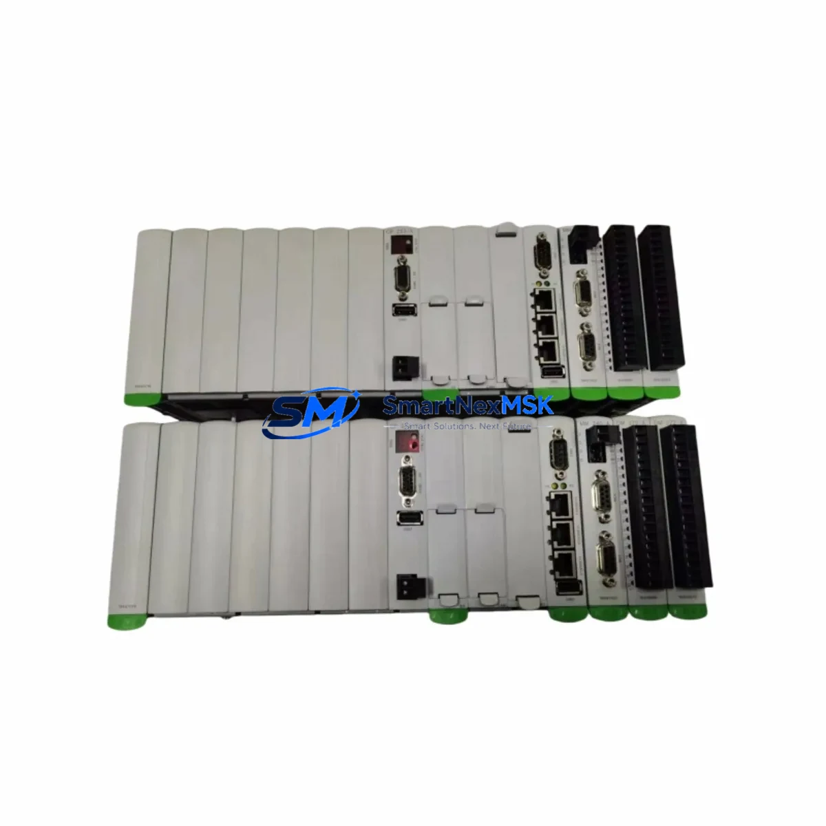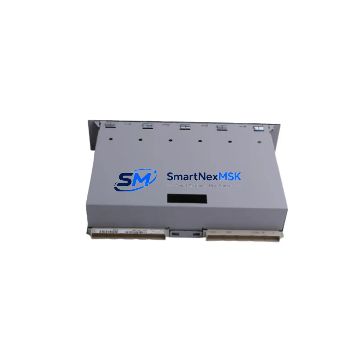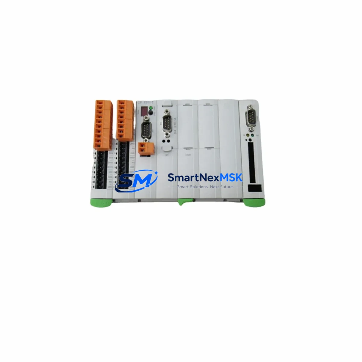
KEBA K2-200 Maintenance-Ready Spare for K2 Automation
The KEBA K2-200 is a core programmable logic controller module within the KEBA K2 Series automation platform, widely deployed in industrial machinery, packaging lines, press control systems, and motion-critical applications across European and global manufacturing facilities. For maintenance engineers managing aging control cabinets or procurement teams building strategic spare parts inventories, the K2-200 represents a high-priority replacement component — one whose failure can trigger immediate production downtime if no verified spare is on hand.
Sourced as an original KEBA unit, this K2-200 spare is pre-tested prior to shipment, ensuring electrical integrity and firmware compatibility with existing K2 Series installations. Whether you are responding to an unplanned fault, executing a scheduled overhaul, or extending the operational life of a legacy system, having a ready K2-200 in your maintenance stock eliminates the most critical delay in any recovery workflow: sourcing time.
Spare Maintenance Table
| Parameter | Specification |
|---|---|
| SKU / Part Number | K2-200 |
| Brand | KEBA |
| Series | K2 Series |
| Product Type | Programmable Logic Controller (PLC) Module |
| Origin | Austria (AT) |
| Supply Voltage | 24 VDC (nominal, K2 Series standard) |
| Communication Interface | CANopen / proprietary K2 bus (series-dependent) |
| Mounting | DIN rail / K2 backplane slot |
| Operating Temperature | 0°C to +55°C |
| Protection Class | IP20 (cabinet-mounted) |
| Compatibility | KEBA K2 Series control systems; replaces legacy K2-200 units |
| Application | Machine automation, press control, packaging, motion systems |
| Warranty | 12 Months — covers manufacturing defects and functional failure |
| Pre-shipment Testing | Yes — electrical and functional verification before dispatch |
| Shipping | Global express; ESD-safe packaging |
Maintenance Planning for Continuous Operation
When a K2-200 fault is detected — whether through a watchdog alarm, communication dropout, or I/O scan failure — the replacement workflow extends well beyond swapping the CPU module itself. Experienced maintenance engineers know that a single controller fault often signals stress across adjacent components in the same control cabinet.
Before or during a K2-200 replacement, it is standard practice to inspect the K2 Series power supply module (typically a 24 VDC regulated unit feeding the backplane) for output ripple or undervoltage conditions that may have contributed to the controller fault. The K2 backplane or rack assembly should be checked for connector oxidation or mechanical damage, as poor backplane contact is a common root cause of intermittent PLC faults in older installations.
I/O integrity is equally critical: the K2 digital input modules and K2 digital output modules installed in adjacent slots should be verified for correct addressing and signal response after the CPU is replaced. If the system uses K2 analog I/O modules for process variable monitoring, recalibration or signal verification against known references is recommended post-replacement.
For systems with fieldbus connectivity, the CANopen communication module or PROFIBUS DP interface card associated with the K2 platform should be inspected for node address conflicts and bus termination integrity — a replaced CPU may require re-initialization of network parameters. If an operator panel or HMI terminal is connected to the K2-200 via serial or Ethernet link, verify communication re-establishment after controller restart.
Additionally, inspect the 24 VDC fuse blocks and terminal strips within the cabinet for signs of thermal stress or loose connections, and confirm that any signal isolators on analog input channels are functioning within specification. Maintaining a consolidated spare parts kit — including the K2-200, associated I/O modules, power supply, and communication components — is the most effective strategy for minimizing mean time to repair (MTTR) in K2 Series-based systems.
Site Replacement Workflow
Replacing a KEBA K2-200 in a live industrial environment requires a structured approach to avoid configuration loss and extended downtime:
- Step 1 — Backup: Before powering down, export the current PLC program and parameter set using KEBA’s programming environment (e.g., KAIRO or compatible IEC 61131-3 tool). Confirm the backup is complete and readable.
- Step 2 — Isolation: Isolate the control cabinet from field power. Follow LOTO (Lockout/Tagout) procedures. Label all I/O wiring if not already documented.
- Step 3 — Module Removal: Release the K2-200 from the backplane slot. Note firmware version label on the outgoing unit for reference.
- Step 4 — Spare Installation: Insert the replacement K2-200. Confirm backplane connector seating. Restore power to the controller only (not field outputs) for initial boot verification.
- Step 5 — Program Restore: Download the backed-up program to the new module. Verify I/O mapping, communication node addresses, and motion parameters match the original configuration.
- Step 6 — Functional Test: Run a controlled test cycle with field outputs enabled. Confirm all I/O, communication links, and HMI displays respond correctly before returning to production.
- Step 7 — Documentation: Record the replacement date, serial number of the new unit, and any configuration changes in the maintenance log. Reorder a spare K2-200 to restore inventory buffer.
This workflow is compatible with both emergency replacements and planned maintenance windows, and is designed to keep total downtime under two hours for a prepared maintenance team.
Spare Parts Support FAQ
Q1: Is this K2-200 an original KEBA unit or a compatible substitute?
This is an original KEBA K2-200 module — not a third-party compatible or remanufactured substitute. Each unit is sourced through verified supply channels and undergoes pre-shipment functional testing to confirm it meets KEBA’s original performance specifications.
Q2: What does the 12-month warranty cover?
The 12-month warranty covers manufacturing defects and functional failures under normal operating conditions. It does not cover damage resulting from incorrect installation, overvoltage events, or physical mishandling. Warranty claims are processed with full technical support from our team.
Q3: How do I confirm compatibility before ordering?
Compatibility is confirmed by matching the full SKU (K2-200), the KEBA K2 Series platform designation, and the backplane slot configuration of your existing system. If you have a system drawing or existing module label, our technical team can verify fit before shipment. Contact us at [email protected] with your system details.
Q4: What is your typical lead time and shipping method?
In-stock units ship within 1–3 business days via international express courier (DHL, FedEx, or equivalent). ESD-safe packaging is standard. For urgent downtime recovery orders, same-day dispatch is available upon request — contact us directly to confirm stock status and arrange priority shipping.
© 2026 SMARTNEXMSK. All rights reserved.
Original Source: https://smartnexmsk.com
Contact: [email protected] | +86 18259474341