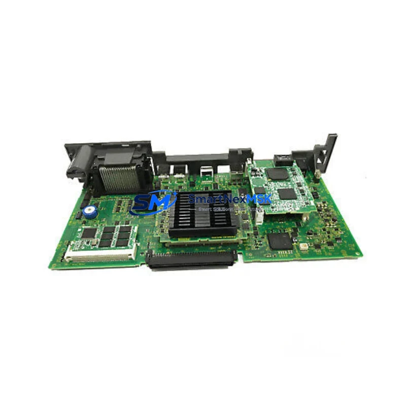
Lam Research 50020R-10 Retrofit-Ready PS/AUX Node Power Supply: Seamless Compatibility for Legacy System Upgrades
The Lam Research 50020R-10 is a PS/AUX Node Power Supply module engineered for semiconductor process equipment platforms. As original Lam Research systems age and OEM spare parts become increasingly scarce, the 50020R-10 has emerged as a critical retrofit component for facilities managing legacy etch and CVD tool fleets. Whether you are replacing a failed unit on a running production line or proactively stocking spares ahead of a planned maintenance window, the 50020R-10 delivers the electrical performance and form-factor compatibility required for a smooth, low-risk swap.
SMARTNEXMSK maintains verified inventory of the 50020R-10 with full functional testing prior to shipment. Each unit is covered by a 12-month warranty and ships with documentation to support your incoming inspection and installation qualification (IQ) process.
Upgrade Compatibility Table
| Parameter | Details |
|---|---|
| Part Number | 50020R-10 |
| OEM Brand | Lam Research |
| Module Function | PS/AUX Node Power Supply |
| Compatible Platform | Lam Research TCP, Exelan, 2300 Series, Rainbow Series etch and CVD systems |
| Interface / Connector | OEM-matched backplane connector; direct drop-in replacement for original mounting position |
| Installation Requirement | No mechanical modification required; verify input voltage rail and ground continuity before power-on |
| Communication Compatibility | Compatible with existing node communication architecture; no firmware re-flash required in standard replacement scenarios |
| Replacement Recommendation | Direct replacement for failed or end-of-life 50020R-10 units; suitable for planned preventive maintenance swap |
| Commissioning Focus | Verify output voltage rails, node address assignment, and interlock signal continuity post-installation |
| Warranty | 12 months from date of shipment; covers manufacturing defects and functional failure under normal operating conditions |
Retrofit Planning for Existing Automation Systems
Replacing the 50020R-10 in a live production environment requires careful pre-work to avoid unplanned downtime and protect the integrity of the surrounding system. Before pulling the failed module, engineers should document the current node address configuration and verify that the replacement unit carries the same revision level or a confirmed compatible revision. The PS/AUX node interfaces directly with the system’s main power distribution backplane, so confirming input voltage tolerance and current draw against the tool’s power budget is essential before energizing the new module.
In many Lam Research tool architectures, the PS/AUX node works in close coordination with the RF match network power supply and the process module controller board. If the system has been running with a degraded 50020R-10 for an extended period, it is advisable to inspect adjacent components — including the node communication cable assembly, the backplane edge connector, and the local fuse block — for signs of thermal stress or arcing before installing the replacement. Overlooking these upstream and downstream components is a common cause of repeat failures after a power supply swap.
For facilities managing multiple Lam Research tools, a coordinated retrofit plan should also account for the status of related modules such as the RF generator interface board, the match controller module, the process kit lift motor driver, and the chamber pressure control valve driver card. These components share the same power distribution architecture and are subject to similar aging profiles. Addressing them as part of a scheduled upgrade cycle — rather than reactively after failure — significantly reduces the risk of cascading downtime across the tool fleet.
Wiring adaptation is rarely required for a direct 50020R-10 replacement, but technicians should verify terminal torque specifications on the input connector block and confirm that the ground strap between the module chassis and the tool frame is intact and corrosion-free. In older installations where the original wiring harness has been repaired or extended, a point-to-point continuity check against the tool’s wiring diagram is strongly recommended before power-on.
If the retrofit is part of a broader control system modernization — for example, migrating from an older Lam Research system controller to a newer platform — additional steps are required to validate program compatibility. The node address map used by the legacy controller software must be preserved or remapped in the new control environment. In some cases, the HMI screen layouts and alarm setpoint configurations associated with the PS/AUX node will also need to be reviewed and updated to reflect the new module’s output characteristics. Engaging the OEM’s field service documentation or a qualified third-party retrofit specialist is advisable for these more complex migration scenarios.
Downtime Control During System Migration
Minimizing tool downtime during a 50020R-10 replacement begins with preparation, not execution. The most effective approach is to stage the replacement unit on-site before the maintenance window opens, complete all incoming inspection steps — including visual inspection, dimensional verification, and bench-level power-on testing — and have all required tools, torque specifications, and wiring diagrams ready at the point of use.
For facilities operating under tight cycle time constraints, a hot-spare strategy is recommended: maintain at least one tested and certified 50020R-10 in local inventory so that a failed unit can be swapped within a single shift without waiting for inbound logistics. SMARTNEXMSK supports this strategy by offering verified, shelf-ready units with short lead times and consistent stock availability.
During the swap itself, the original program logic stored in the system controller is not affected by a power supply module replacement, provided the node address and communication parameters are preserved. Technicians should record the pre-swap node status from the HMI or engineering terminal before de-energizing the module, and verify that the same status is restored after the replacement unit is installed and powered. This step protects against inadvertent changes to interlock logic or process recipe parameters that could affect the first wafer run after restart.
Post-installation commissioning should include a full node communication check, output voltage verification across all rails, and a supervised process run at reduced recipe parameters before returning the tool to full production. Documenting the commissioning results and retaining them with the tool’s maintenance record supports future troubleshooting and demonstrates due diligence for quality system audits.
Retrofit Support FAQ
Q1: Is the 50020R-10 a direct drop-in replacement for the original Lam Research unit?
Yes. The 50020R-10 supplied by SMARTNEXMSK is form-fit-function compatible with the original OEM part. No mechanical modification or wiring adaptation is required for a standard replacement in the original mounting position. Each unit is functionally tested prior to shipment to confirm output voltage compliance and communication interface integrity.
Q2: What commissioning steps are required after installation?
After installing the replacement 50020R-10, technicians should verify node address assignment, confirm output voltage on all rails using a calibrated meter, check interlock signal continuity, and perform a supervised process run before returning the tool to production. The node communication status should be confirmed from the HMI or engineering terminal. Any deviation from expected values should be investigated before full production restart.
Q3: Can the 50020R-10 be used in a system that has been upgraded with a newer controller platform?
In most cases, yes — provided the node communication protocol and address map are compatible with the upgraded controller. For systems that have undergone significant control platform migration, it is advisable to verify compatibility with the new controller’s node management software before installation. SMARTNEXMSK’s technical support team can assist with compatibility assessment based on your specific tool configuration.
Q4: What does the 12-month warranty cover?
The 12-month warranty covers manufacturing defects and functional failure under normal operating conditions from the date of shipment. It includes repair or replacement of the defective unit at no additional charge. The warranty does not cover damage resulting from incorrect installation, operation outside specified parameters, or physical mishandling. All warranty claims are processed directly through SMARTNEXMSK.
© 2026 SMARTNEXMSK. All rights reserved.
Original Source: https://smartnexmsk.com
Contact: [email protected] | +86 18259474341