Lam Research 810-068158-014 Spare for Node Automation: Spare Replacement & Downtime Risk Control
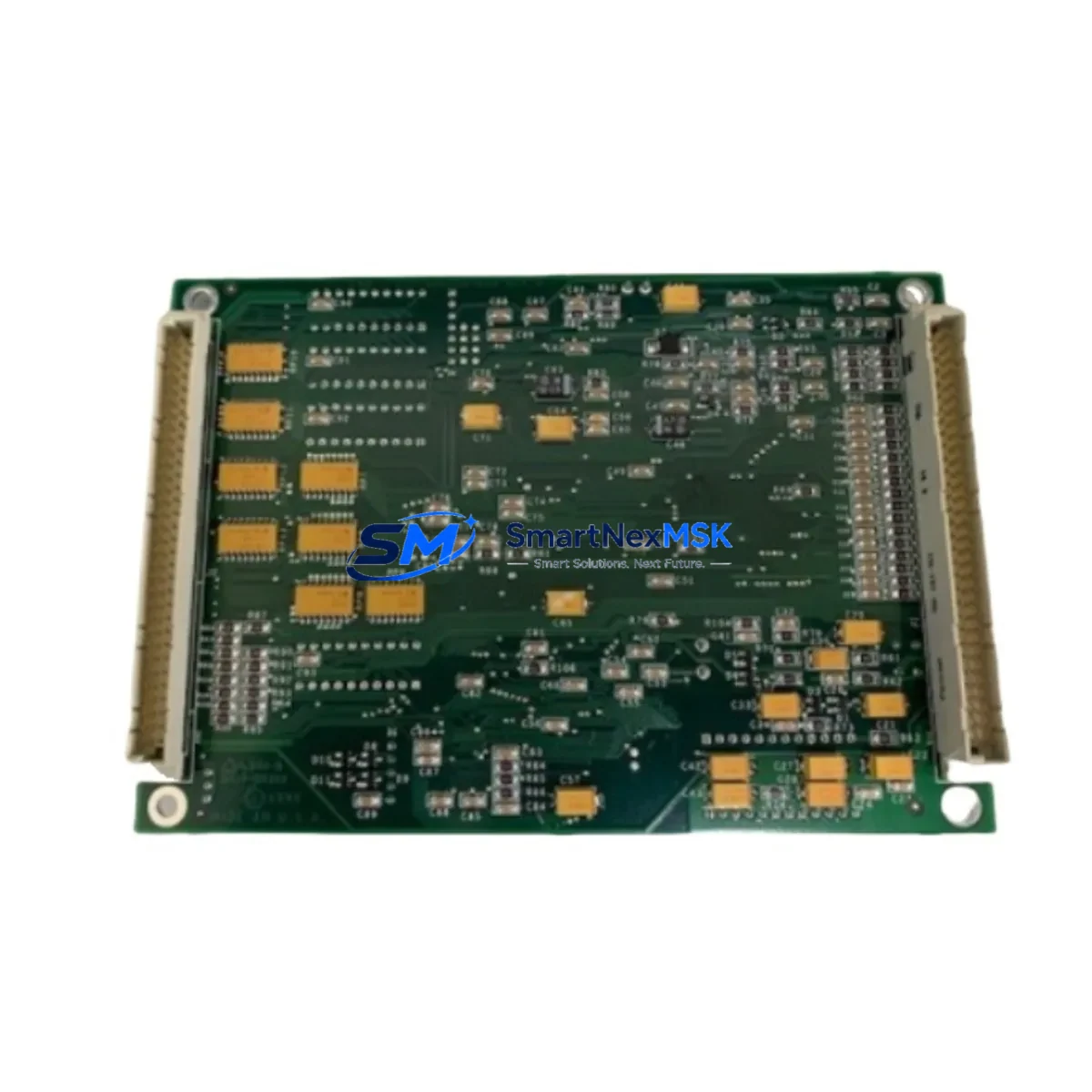
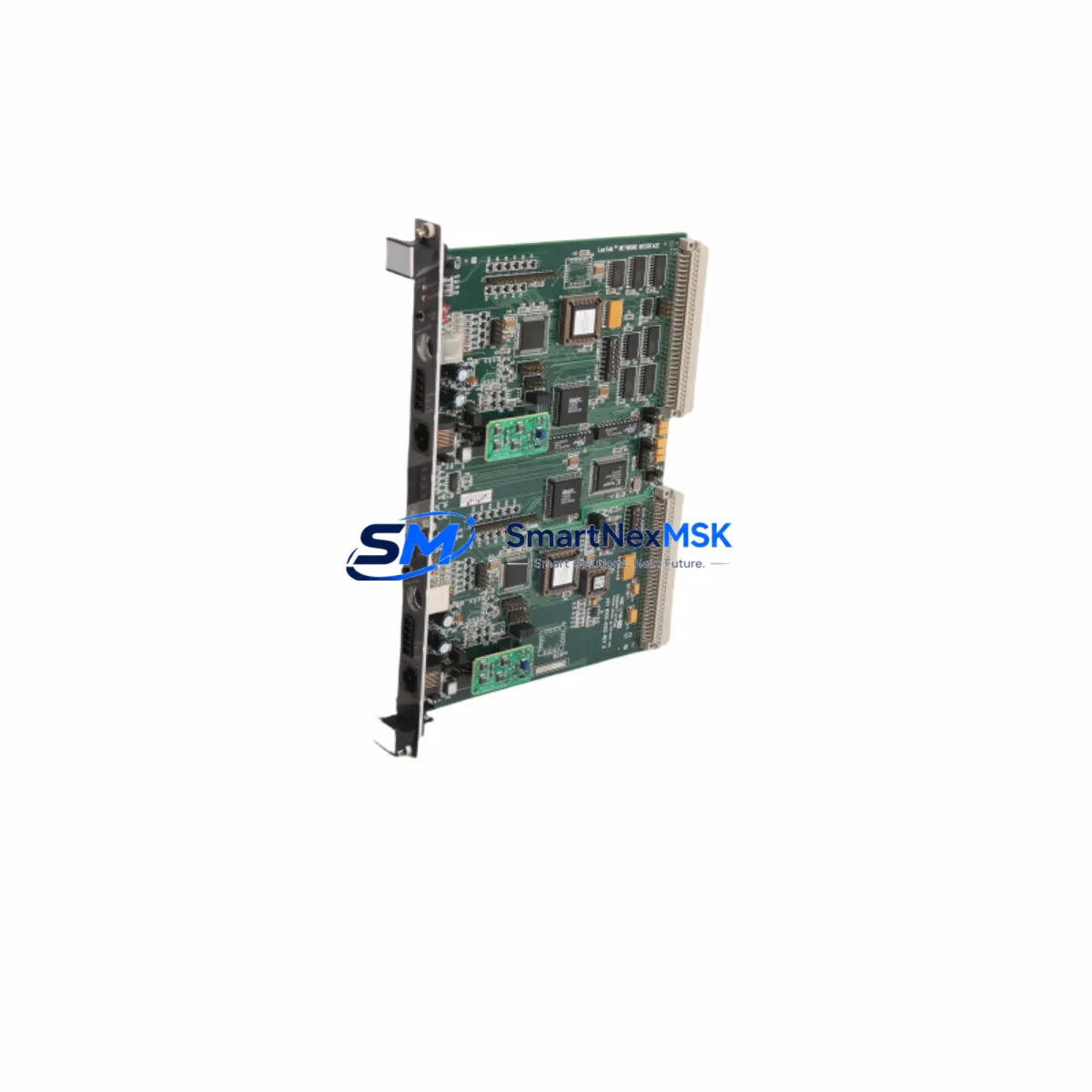
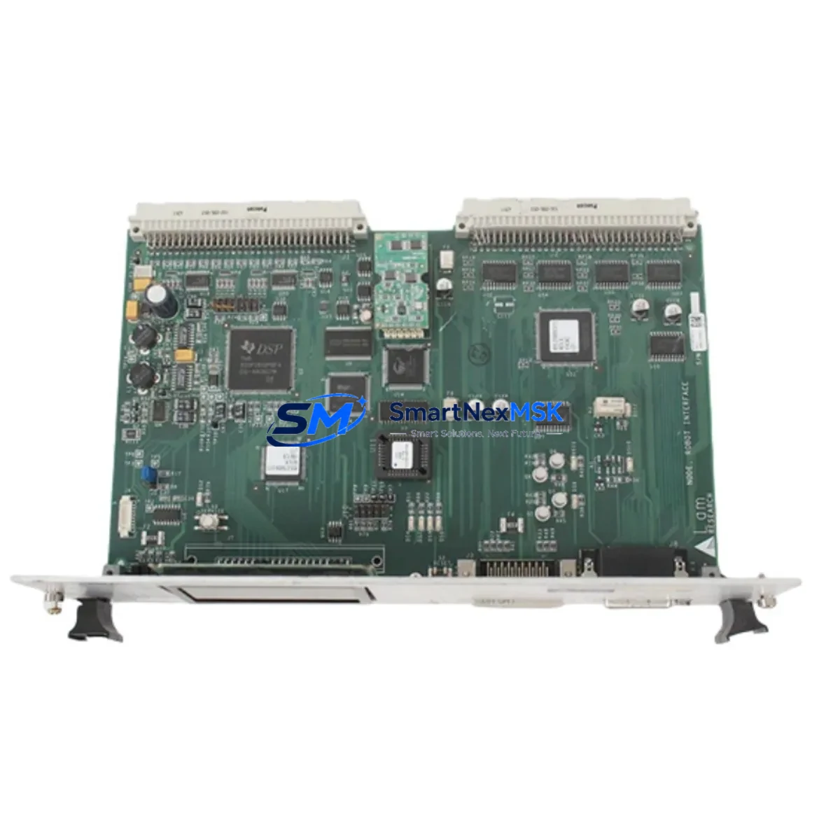
The Lam Research 810-068158-014 is an original Node Robot Interface Board designed for semiconductor wafer transfer automation systems. As a critical communication and control bridge between the robot arm controller and the process chamber node, this board is a high-priority spare for any facility operating Lam Research etch or deposition platforms. Unplanned failure of this interface board can halt wafer transfer sequences entirely, resulting in costly unscheduled downtime and potential wafer loss. Stocking a verified replacement unit is the most effective strategy for rapid recovery and sustained throughput.
This unit is sourced as an original Lam Research spare, tested prior to shipment, and backed by a 12-month warranty. It is suitable for direct replacement in compatible Node-architecture tool configurations. Maintenance engineers and procurement teams can rely on this board for both emergency swap-out and planned preventive maintenance cycles.
Spare Maintenance Table
| Part Number | 810-068158-014 |
| Brand | Lam Research |
| Series / Platform | Node Automation / Wafer Transfer System |
| Product Type | Robot Interface Board |
| Function | Robot arm-to-node controller communication interface |
| Compatibility | Lam Research Node-architecture etch and CVD platforms |
| Origin | United States (OEM) |
| Installation | Direct board-level replacement; follow ESD precautions |
| Operating Environment | Cleanroom-compatible; semiconductor fab environment |
| Maintenance Recommendation | Inspect connectors and ribbon cables at each PM cycle; replace if communication faults are logged |
| Condition | Original spare; pre-shipment functional test |
| Warranty | 12 Months |
| Lead Time | In stock; ships within 1–3 business days |
Maintenance Planning for Continuous Operation
When replacing the 810-068158-014 Node Robot Interface Board, a thorough maintenance engineer will treat the swap as an opportunity to audit the surrounding electrical and control architecture. The robot interface board does not operate in isolation — it is part of an interconnected system where adjacent components can mask or amplify faults.
Begin by inspecting the robot arm power supply module that feeds the Node controller. Voltage instability or ripple at the supply rail is a common root cause of interface board degradation over time. Simultaneously, check the Node controller backplane for oxidized edge connectors or cracked solder joints, as these can cause intermittent communication errors that are often misdiagnosed as board failure.
The ribbon cable assemblies and I/O harnesses connecting the interface board to the robot arm encoder and limit switch circuits should be inspected for chafing, connector pin retraction, and insulation breakdown — particularly in high-cycle environments. Replace any harness showing visible wear.
Review the 24VDC I/O distribution terminal blocks in the control cabinet. Loose terminations at these points can introduce ground loops that corrupt serial communication signals passing through the interface board. A torque check and continuity test across all I/O terminals is recommended as part of the same PM event.
If the tool uses a Lam Research Node communication module (such as a SECS/GEM or EtherCAT gateway card), verify that firmware versions are compatible with the replacement board revision. Mismatched firmware can cause handshake failures even when the hardware is fully functional.
Check the signal isolation barriers on any analog sensor inputs feeding the Node controller. Degraded isolators can allow noise from the RF power supply or vacuum pump drives to couple into the control signal path, causing spurious fault trips that are difficult to trace without proper isolation testing.
Inspect the 24V relay output modules that drive end-effector solenoids and blade sensors. These relays accumulate switching cycles and should be evaluated for contact resistance at the same interval as the interface board replacement. A failed relay output can prevent the robot from completing its pick-and-place sequence even after the interface board is restored.
Finally, verify the HMI communication link between the Node controller and the operator panel. After board replacement, re-establish the communication parameters and confirm that all robot status signals — home position, fault codes, and cycle count — are correctly displayed. This step is critical before returning the tool to production.
Site Replacement Workflow
Step 1 — Isolation: Place the tool in maintenance mode via the HMI. Confirm that the robot arm is in the home position and that all wafer transfer sequences are halted. Lock out the robot controller power per your facility LOTO procedure.
Step 2 — ESD Preparation: Don ESD wrist strap and mat. The 810-068158-014 is a static-sensitive PCB assembly. Handle only by the board edges and avoid contact with connector pins or component surfaces.
Step 3 — Removal: Disconnect all ribbon cables and I/O harnesses from the existing board. Note or photograph connector positions before removal. Unscrew the board retention hardware and slide the board out of the Node controller chassis.
Step 4 — Installation: Seat the replacement 810-068158-014 board into the chassis slot. Secure retention hardware to the specified torque. Reconnect all harnesses in the documented order. Verify that all connectors are fully seated and latched.
Step 5 — Power-Up and Verification: Restore controller power. Monitor the HMI for fault codes during the boot sequence. Run the robot through a manual jog cycle to confirm all axes respond correctly. Execute a full automated transfer sequence in simulation mode before returning to production.
This workflow minimizes tool downtime to under two hours for a prepared maintenance team and eliminates the risk of re-work caused by incorrect reassembly. Compatibility with the existing Node platform is maintained without firmware changes in most standard revision configurations.
Spare Parts Support FAQ
Q1: What is the warranty coverage for the 810-068158-014?
This unit carries a 12-month warranty from the date of shipment. Coverage includes functional failure under normal operating conditions. Each unit undergoes pre-shipment functional testing to verify board-level operation before dispatch.
Q2: How do I confirm compatibility with my specific Lam Research tool configuration?
Provide your tool serial number, Node controller revision, and current board part number (including the dash suffix) when placing your inquiry. Our technical team will cross-reference against known compatible configurations and confirm fit before shipment.
Q3: What is the recommended spare parts inventory strategy for this board?
For facilities operating two or more Lam Research Node-platform tools, we recommend maintaining a minimum of one 810-068158-014 on-site as a cold spare. Given the board’s role in wafer transfer continuity, a single unplanned failure without a spare on hand can result in 24–72 hours of downtime while awaiting emergency procurement.
Q4: Can this board replace older or superseded Lam Research Node interface board revisions?
In many cases, yes. The -014 revision is a later production release and is backward-compatible with earlier Node controller chassis in the same platform family. However, compatibility should always be confirmed against your specific tool BOM before installation. Contact our team with your existing part number for a formal cross-reference.
© 2026 SMARTNEXMSK. All rights reserved.
Original Source: https://smartnexmsk.com
Contact: sales@smartnexmsk.com | +86 18259474341