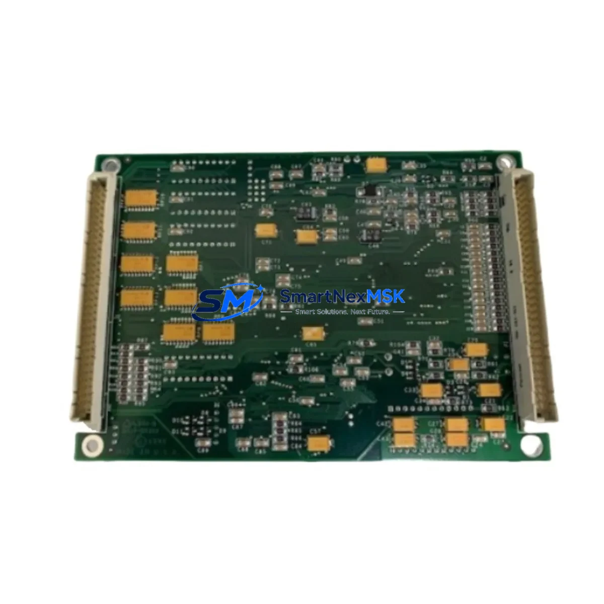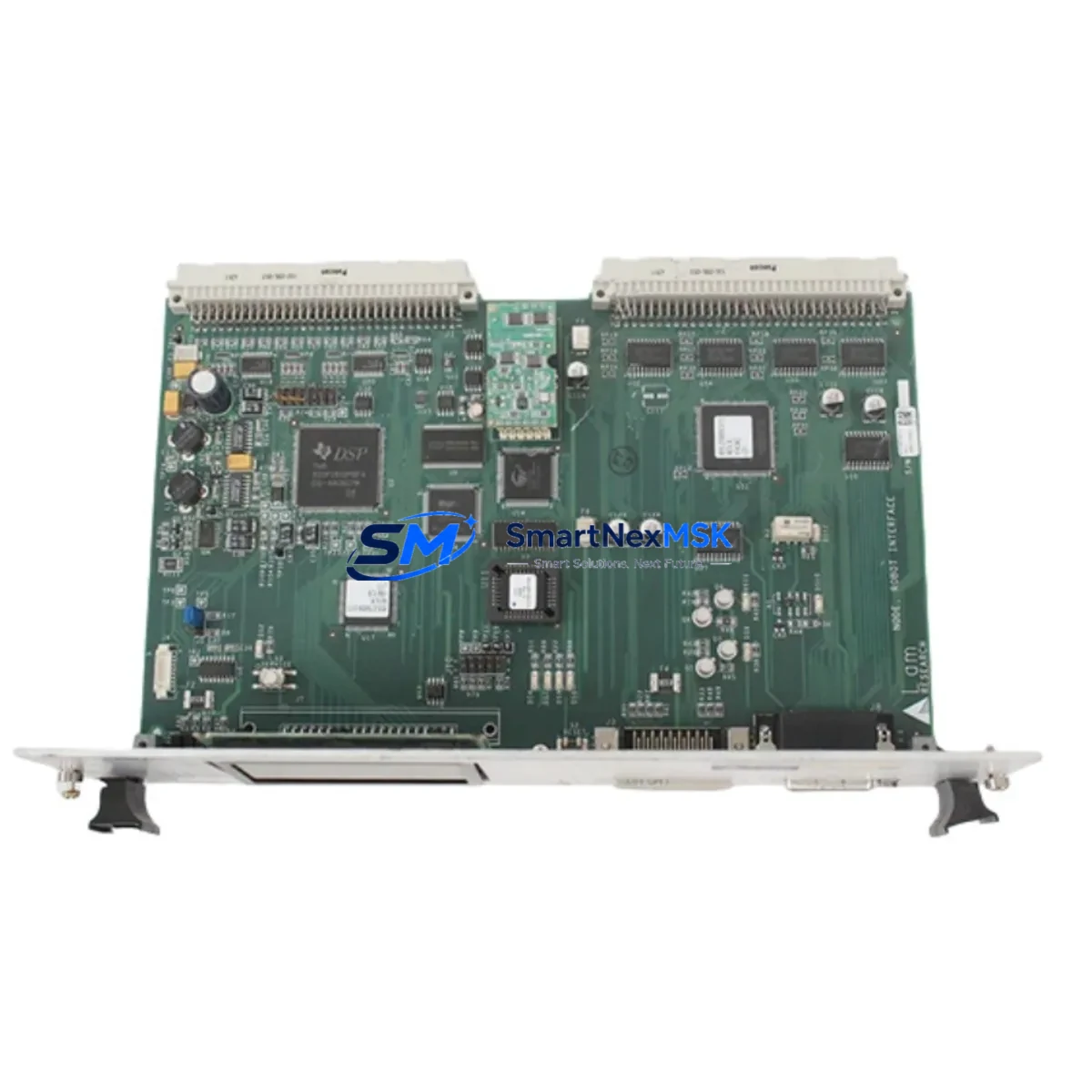
LAM Research VME-LTNI-S4 B105-0102: Retrofit-Ready VME Network Interface for Legacy Control System Upgrades
The LAM Research VME-LTNI-S4 B105-0102 is a VME-bus network interface board engineered for integration into LAM Research semiconductor processing equipment and legacy VME-based control architectures. As original LAM Research systems age and OEM support windows close, this module has become a critical retrofit component for facilities maintaining CVD, etch, and deposition platforms that rely on VME backplane communication infrastructure. Our stock is sourced, inspected, and shipped with a 12-month warranty, providing a reliable path for engineers managing end-of-life system continuity.
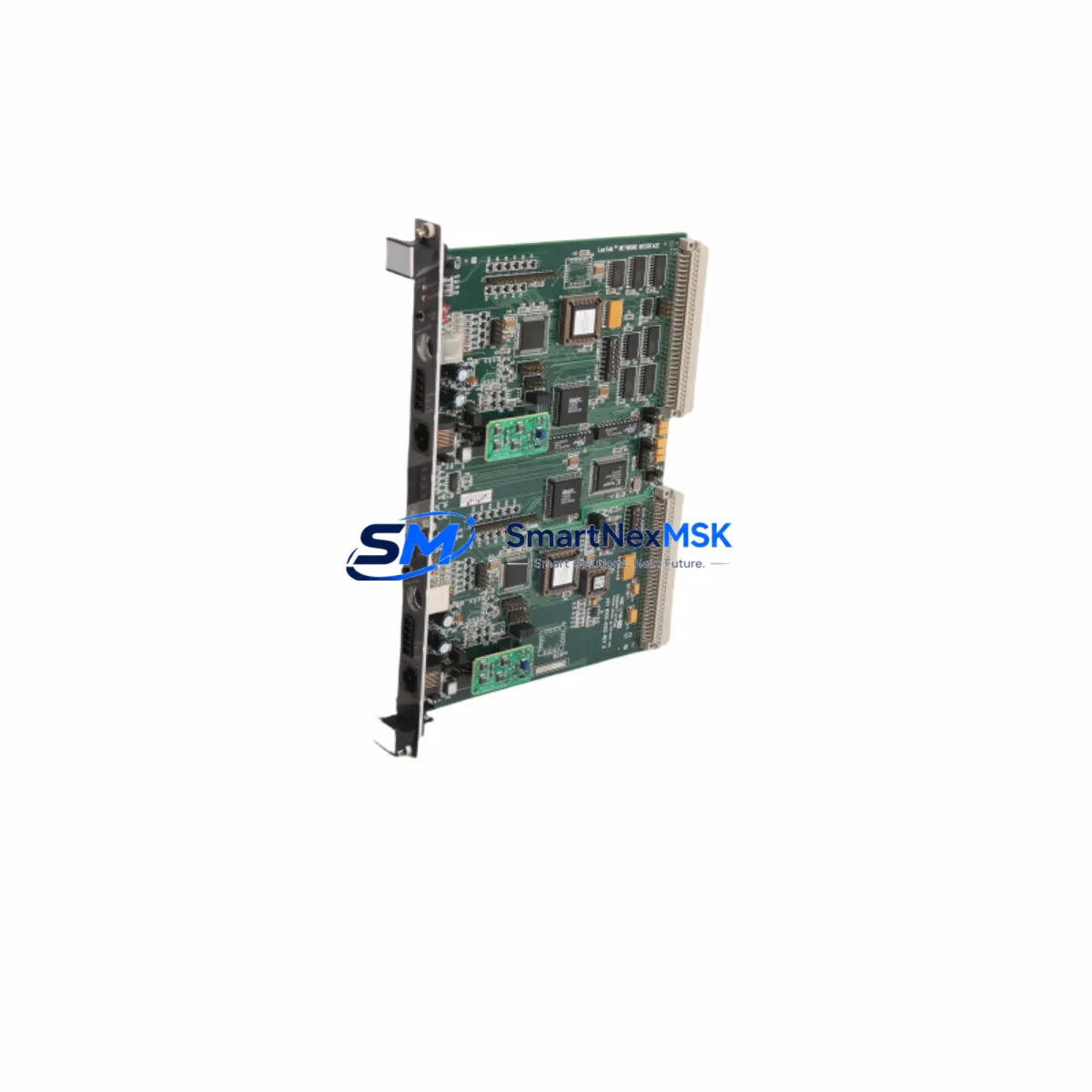
Whether you are replacing a failed board in an active production tool, upgrading a control cabinet to extend service life, or migrating a legacy VME platform to a modernized control architecture, the VME-LTNI-S4 B105-0102 serves as a direct retrofit solution. Its VME64 form factor ensures physical compatibility with standard 6U VME racks and backplanes commonly found in LAM Research Transformer Coupled Toroidal (TCP) and Rainbow series tools.
Upgrade Compatibility Table
| Parameter | Details |
|---|---|
| Part Number | VME-LTNI-S4 B105-0102 |
| OEM / Brand | LAM Research |
| Board Form Factor | 6U VME64 (IEEE 1014) |
| Backplane Interface | VMEbus P1/P2 connector, 96-pin DIN 41612 |
| Network / Communication | LTNI (LAM Tool Network Interface) proprietary protocol over VME |
| Compatible Systems | LAM Research TCP, Rainbow, 2300 series etch and CVD platforms |
| Installation Requirement | Slot assignment must match original chassis address map; verify jumper/DIP switch settings before installation |
| Power Requirement | +5 VDC, ±12 VDC via VME backplane; verify PSU capacity before hot-swap or cold-swap installation |
| Replacement Recommendation | Direct drop-in for failed or end-of-life VME-LTNI-S4 boards; no firmware re-flash required in most configurations |
| Commissioning Focus | Module address verification, LTNI link status, I/O handshake confirmation with host controller |
| Warranty | 12 months from date of shipment; covers manufacturing defects and functional failure under normal operating conditions |
Retrofit Planning for Existing Automation Systems
Successful integration of the VME-LTNI-S4 B105-0102 into an existing control system requires a structured pre-installation audit. Engineers should begin by documenting the current VME chassis slot map, confirming which slots are occupied by the VME CPU board (typically a Motorola MVME162 or MVME167 series), VME digital I/O modules, and any VME analog output boards handling process setpoint signals. The LTNI network interface occupies a dedicated slot and communicates upstream to the host workstation or process controller via the LAM proprietary tool network.
Before removing the failed board, capture the current DIP switch and jumper configuration using a photograph or written record. The module base address and interrupt level settings on the VME-LTNI-S4 must match the original board exactly to avoid address conflicts with co-resident VME modules such as the VME digital I/O board or VME timer/counter module. Mismatched addressing is the most common cause of post-replacement communication faults.
Power budget verification is essential. The VME backplane power supply module must have sufficient headroom on the +5 VDC rail to support the replacement board. In aging systems, capacitor degradation in the PSU can cause marginal rail voltages that trigger intermittent faults on newly installed boards. Measure rail voltages under load before and after installation.
For facilities running LAM SPARC-based workstations or transitioning to modern Linux-based host controllers, confirm that the LTNI driver stack is compatible with the replacement board’s firmware revision. In some 2300 series configurations, the host software references a specific board revision identifier during initialization; a mismatch may require a software configuration file update rather than a firmware change on the board itself.
If the retrofit is part of a broader control cabinet upgrade — for example, migrating from a legacy VME crate controller to a modern Siemens S7-300 or Allen-Bradley ControlLogix PLC gateway — the LTNI interface may need to be bridged through a protocol converter. In such cases, the VME-LTNI-S4 B105-0102 can serve as the VME-side anchor while the new control layer communicates via Ethernet/IP or PROFIBUS DP, depending on the target architecture. The VME-to-PLC gateway module, associated PROFIBUS DP communication card, and programming cable for the new controller should be staged and tested offline before the production cutover window.
Terminal wiring on any field I/O connected through the VME I/O subsystem should be re-verified against the original wiring diagram. Label all terminal blocks before disconnection. If the system includes a VME analog input board for process sensor signals (pressure, temperature, flow), confirm that signal conditioning ranges are unchanged after the network interface replacement, as some LAM configurations use the LTNI board to relay calibration parameters to analog modules at startup.
HMI screens on the operator workstation — whether running on a legacy LAM process control console or a modernized SCADA/HMI panel — should be validated post-replacement. The LTNI link status indicator in the LAM process control software must show an active connection before recipe execution is permitted. If the HMI displays a “Tool Network Fault” alarm after board replacement, the first diagnostic step is to verify the LTNI cable seating at both the board front-panel connector and the workstation interface card.
Downtime Control During System Migration
Minimizing unplanned downtime during a VME-LTNI-S4 B105-0102 replacement requires preparation that begins before the maintenance window opens. The recommended approach is to pre-configure the replacement board offline — setting DIP switches, verifying jumper positions, and confirming firmware revision — so that the physical swap can be completed within a single scheduled maintenance slot.
Before powering down the VME chassis, save a full backup of the process recipe library and any tool-specific calibration files stored on the host workstation. In LAM Research systems, recipe data is typically stored on the workstation rather than on the VME board itself, but LTNI configuration parameters may be embedded in tool initialization scripts that reference board-specific identifiers. Retain copies of these scripts before the swap.
During the swap, follow ESD precautions rigorously. VME network interface boards are sensitive to electrostatic discharge, and latent ESD damage can cause intermittent failures that are difficult to diagnose post-installation. Use a grounded wrist strap and handle the board by its ejector handles rather than by the PCB surface.
After installation, power up the VME chassis with the host workstation disconnected from the LTNI network. Verify that the board initializes correctly by observing the front-panel LED indicators — a steady link LED confirms that the board has passed its internal self-test. Reconnect the LTNI cable and confirm host-to-tool communication before loading any process recipes. This staged power-up sequence protects the original program logic from being overwritten by an incomplete initialization handshake.
For facilities that cannot afford a cold-swap window, a parallel-chassis strategy — staging a pre-configured spare VME crate with the replacement board installed and tested — allows a hot-cutover in under 30 minutes. This approach is particularly effective for high-utilization etch tools where unscheduled downtime carries significant production cost.
All replacement boards shipped by SMARTNEXMSK undergo functional testing prior to dispatch. Each unit is verified for VMEbus signal integrity, LTNI link establishment, and power rail compliance. A test report is available upon request. The 12-month warranty covers functional failure under normal operating conditions and provides a clear remediation path if post-installation issues arise.
Retrofit Support FAQ
Q1: Is the VME-LTNI-S4 B105-0102 a direct replacement for the original LAM Research board?
Yes. The VME-LTNI-S4 B105-0102 is a form-fit-function replacement for the original LAM Research network interface board of the same part number. No mechanical modification to the VME chassis is required. Jumper and DIP switch settings from the original board must be replicated on the replacement unit before installation.
Q2: What commissioning steps are required after installation?
After physical installation, verify the module base address and interrupt level settings match the original configuration. Power up the VME chassis and confirm front-panel LED status. Reconnect the LTNI cable and verify host-to-tool communication in the LAM process control software. Run a dry-cycle recipe (no process gas or RF) to confirm I/O handshake and recipe execution before returning the tool to production.
Q3: Can this board be used in a system that has been partially upgraded to a modern PLC or DCS architecture?
Yes, in hybrid retrofit configurations. The VME-LTNI-S4 B105-0102 can coexist with modern control layers as long as the VME backplane remains active. If the VME subsystem is being retired entirely, a protocol bridge or gateway module will be required to translate LTNI communications to the target control network (e.g., Ethernet/IP, PROFIBUS DP, or Modbus TCP).
Q4: What does the 12-month warranty cover, and what is the process for a warranty claim?
The 12-month warranty covers manufacturing defects and functional failure under normal operating conditions from the date of shipment. It does not cover damage resulting from incorrect installation, ESD mishandling, or operation outside specified voltage and environmental ranges. To initiate a warranty claim, contact sales@smartnexmsk.com with the order number, a description of the fault, and any available diagnostic data. Replacement or repair will be arranged within 5 business days of claim confirmation.
© 2026 SMARTNEXMSK. All rights reserved.
Original Source: https://smartnexmsk.com
Contact: sales@smartnexmsk.com | +86 18259474341