Mitsubishi A1SJ71AR2 Maintenance-Ready Spare for MELSEC-A: Spare Replacement & Industrial Downtime Risk Control
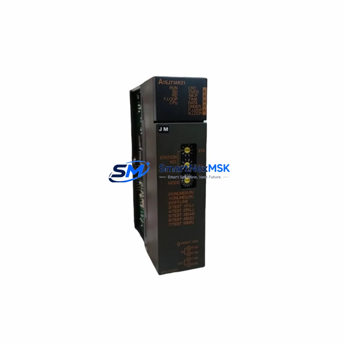
The Mitsubishi Electric A1SJ71AR2 is a MELSEC-A Series data link module designed for high-reliability industrial communication in PLC-based control systems. As a maintenance-ready original spare part, the A1SJ71AR2 supports AR network data link communication, enabling deterministic, cyclic data exchange between MELSEC-A Series CPUs and remote I/O stations across manufacturing lines, process plants, and utility infrastructure. When a data link module fails, the entire communication backbone of a control cabinet can go silent — halting production, triggering safety shutdowns, and extending unplanned downtime. Stocking a verified A1SJ71AR2 spare is the single most effective step a maintenance team can take to protect system uptime.
This unit is sourced as an original Mitsubishi Electric component, individually tested prior to dispatch, and backed by a 12-month warranty. It is suitable for direct replacement in existing MELSEC-A Series control panels without firmware reconfiguration in most standard AR network topologies.
Spare Maintenance Table
| Parameter | Specification |
|---|---|
| Part Number / SKU | A1SJ71AR2 |
| Brand | Mitsubishi Electric |
| Series | MELSEC-A (AnS Series) |
| Module Type | Data Link Module (AR Network) |
| Communication Protocol | MELSEC-A AR Network (cyclic / transient) |
| Applicable CPU | A1SCPU, A1SHCPU, A2SCPU, A2SHCPU and compatible AnS CPUs |
| Mounting | AnS Series slim base unit (A1S-series backplane) |
| Power Consumption | Refer to Mitsubishi MELSEC-A hardware manual |
| Operating Temperature | 0°C to 55°C |
| Storage Temperature | -20°C to 75°C |
| Origin | Japan |
| Compatibility | MELSEC-A AnS Series control systems; AR network topology |
| Warranty | 12 Months — tested and verified before shipment |
| Condition | Original spare — new or fully refurbished to OEM standard |
Maintenance Planning for Continuous Operation
When scheduling planned maintenance or responding to an unplanned fault involving the A1SJ71AR2, maintenance engineers should treat the data link module as part of a broader communication and power subsystem inspection. A failed or degraded AR network module rarely operates in isolation — associated components in the same control cabinet are often under equivalent stress and may be approaching end-of-life simultaneously.
During a cabinet inspection triggered by an A1SJ71AR2 fault, engineers should verify the condition of the A1S61PN power supply module, which provides regulated DC power to the AnS Series base unit. A marginal power supply can cause intermittent data link errors that mimic module failure. Alongside the power supply, the A1SX40 and A1SY40 I/O modules mounted on the same base unit should be checked for contact wear, blown fuses, and wiring integrity at the terminal blocks.
For systems using the A1SJ71AR2 in multi-drop AR network configurations, the A1SJ71AP23Q or A1SJ71UC24-R4 serial communication modules installed in adjacent slots may share the same network segment and should be inspected for communication error flags. If the control system includes an A1SD75P1-S3 positioning module or motion controller on the same backplane, verify that axis communication has not been disrupted by the data link fault.
Terminal blocks and field wiring connected to the AR network should be inspected for loose terminations, corrosion, and impedance mismatches. Signal isolators used on analog input channels feeding the MELSEC-A CPU should be tested for drift, particularly in high-vibration or high-humidity environments. If the system uses an F940GOT or A77GOT HMI panel communicating via the AR network, verify that the HMI communication parameters remain aligned after module replacement.
For older MELSEC-A installations approaching system end-of-life, it is advisable to audit the full spare parts inventory: A1SCPU, A2SCPU CPU modules, base units, and power supplies should all be represented in the critical spares list. Proactive stocking of the A1SJ71AR2 alongside these components significantly reduces mean time to repair (MTTR) and supports long-term system life extension strategies.
Site Replacement Workflow
Step 1 — Isolate and document: Before removing the A1SJ71AR2, record all AR network station numbers, link device assignments, and communication parameters from the existing module and the GX Developer or MELSEC Medoc project file. Take a photograph of the wiring and connector orientation.
Step 2 — Power down safely: De-energize the control cabinet following site lockout/tagout (LOTO) procedures. Confirm that the A1S61PN or equivalent power supply is fully discharged before handling the base unit.
Step 3 — Remove and inspect: Extract the A1SJ71AR2 from its slot. Inspect the backplane connector for bent pins or contamination. Clean the slot with dry compressed air if required.
Step 4 — Install replacement: Seat the new A1SJ71AR2 firmly into the original slot. Reconnect all AR network cables and verify termination resistor placement at network endpoints. Confirm that the station number rotary switches match the documented configuration.
Step 5 — Power up and verify: Restore power and monitor the module’s LED indicators. Use GX Developer or the MELSEC-A diagnostic utility to confirm that the AR network link is established and all remote stations are communicating. Clear any latched error codes in the CPU.
Step 6 — Functional test: Run a full I/O scan and verify that all cyclic data exchanges are operating within expected cycle times. Confirm HMI display data is refreshing correctly before returning the system to production.
This replacement workflow is designed to minimize downtime and ensure system compatibility is maintained without requiring CPU reprogramming or network reconfiguration in standard AR network deployments.
Spare Parts Support FAQ
Q1: Is the A1SJ71AR2 still available as a new original spare?
The MELSEC-A Series has reached end-of-production, but original spare units — new old stock and fully refurbished to OEM specification — remain available through specialist industrial automation suppliers. Each unit supplied by SMARTNEXMSK is individually tested and ships with a 12-month warranty, ensuring it meets the same performance standard as a factory-new module.
Q2: How do I confirm compatibility before ordering?
Compatibility is determined by your base unit type (A1S-series slim base), CPU model (A1SCPU, A2SCPU, or equivalent AnS CPU), and AR network topology. If you can provide your existing module’s station number configuration and the CPU model in your cabinet, our technical team can confirm direct drop-in compatibility before shipment.
Q3: What testing is performed before the A1SJ71AR2 is shipped?
Every A1SJ71AR2 unit undergoes power-on functional testing, AR network communication verification, and visual inspection of the backplane connector and front-panel indicators. Units that do not pass all test criteria are not dispatched. A test report is available upon request for critical maintenance applications.
Q4: What is the recommended spare parts strategy for aging MELSEC-A systems?
For MELSEC-A systems still in active production service, we recommend maintaining at least one A1SJ71AR2 on-site as a critical spare, alongside a CPU module (A1SCPU or A2SCPU), a power supply (A1S61PN), and representative I/O modules for your installed base. This minimum inventory profile covers the highest-failure-risk components and supports a target MTTR of under four hours for most cabinet-level faults.
© 2026 SMARTNEXMSK. All rights reserved.
Original Source: https://smartnexmsk.com
Contact: sales@smartnexmsk.com | +86 18259474341


