Mitsubishi A1SY10 Retrofit-Ready Output Module for MELSEC-A Control Systems
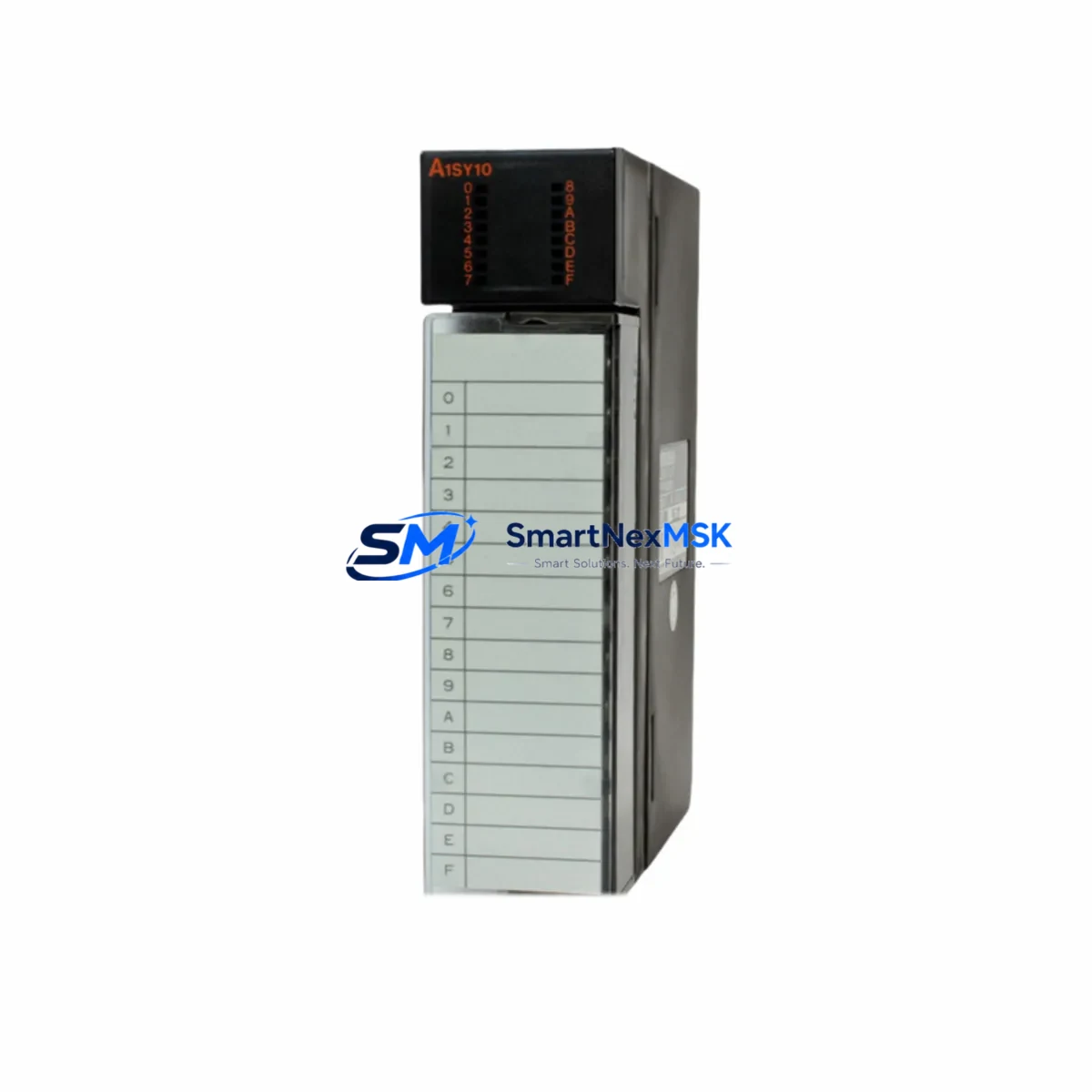
The Mitsubishi A1SY10 is a 16-point transistor (sink) digital output module designed for the MELSEC-A Series programmable logic controller platform. As legacy MELSEC-A systems reach end-of-life and original Mitsubishi Electric production of the A1SY10 has been discontinued, industrial facilities worldwide are actively sourcing verified replacement units to sustain production continuity, execute planned control cabinet upgrades, and avoid unscheduled downtime. SMARTNEXMSK maintains ready stock of the A1SY10, fully tested and backed by a 12-month warranty, to support your retrofit and modernization projects.
Whether you are replacing a failed module in an existing MELSEC-A rack, upgrading a legacy control panel to extend its operational life, or migrating I/O capacity ahead of a phased transition to the MELSEC-Q or MELSEC-iQ-R platform, the A1SY10 provides a direct, wiring-compatible solution that minimizes engineering rework and commissioning time.
Upgrade Compatibility Table
| Parameter | Detail |
|---|---|
| Module Model | Mitsubishi A1SY10 |
| Series | MELSEC-A (AnS / A1S / A2S) |
| Output Type | Transistor Sink, 16 Points |
| Rated Load Voltage | 12–24 VDC |
| Max Load Current | 0.1 A per point / 0.8 A per common |
| Backplane Interface | MELSEC-A slim-series base unit (A1S series) |
| Compatible Base Units | A1S33B, A1S35B, A1S38B, A1S52B, A1S55B, A1S58B |
| Terminal Wiring | 18-point terminal block, compatible with original A1SY10 wiring layout |
| Communication Compatibility | MELSEC-A bus; compatible with A1SCPU, A2SCPU, A2SHCPU CPUs |
| Replacement Recommendation | Direct drop-in replacement; no program modification required |
| Commissioning Notes | Verify module address assignment on base unit; confirm output common wiring polarity |
| Warranty | 12 Months from shipment date |
| Pre-shipment Testing | Full functional output point test performed before dispatch |
Retrofit Planning for Existing Automation Systems
Retrofitting a MELSEC-A control system requires careful coordination across multiple hardware layers. When replacing the A1SY10, engineers should begin by auditing the existing base unit — typically an A1S38B or A1S55B slim-series rack — to confirm available slot positions and verify that the backplane bus is free of corrosion or connector damage that could cause intermittent output faults after module swap.
Power budget verification is a critical pre-installation step. The A1S61PN or A1S62PN power supply module feeding the rack must have sufficient 5 VDC internal bus capacity to support the A1SY10 alongside other installed modules such as input modules (A1SX10, A1SX40) and analog I/O modules (A1S68AD, A1S62DA). Exceeding the power supply’s rated current will cause erratic module behavior and potential CPU faults.
Terminal block wiring should be documented photographically before removal of the legacy module. The A1SY10 uses a standard 18-point removable terminal block, and output commons must be correctly identified — particularly in mixed-voltage panels where 12 VDC and 24 VDC load circuits may share the same cabinet. Confirm that external load wiring polarity matches the sink output configuration before energizing the replacement module.
For systems using MELSEC-A network communication — including CC-Link via an A1SJ61BT11 master/local module or MELSEC-NET/MINI-S3 via an A1SJ71AP23Q — the output module replacement does not affect network configuration, as I/O addressing is managed at the CPU level through the I/O assignment parameters stored in the A1SCPU or A2SHCPU. However, engineers should verify that the I/O assignment table in GX Developer or SW□D5C-GPPW programming software correctly reflects the slot position of the replacement A1SY10 before going live.
In control cabinets where an A1S68TD temperature control module or A1SD75P1-S3 positioning module is co-installed, confirm that the output module address range does not overlap with special function module I/O assignments. HMI screens connected via RS-232 or RS-422 to a GOT1000 or GOT-A900 series panel should be reviewed to ensure that output device tags mapped to the A1SY10’s Y-address range remain valid after the module is reseated.
Where a phased migration to MELSEC-Q is planned, the A1SY10 replacement extends the operational life of the existing A1S platform while the migration project is engineered. This approach avoids forced emergency upgrades and allows the transition to Q-series hardware — including QX40 input modules, QY10 output modules, and Q02UCPU controllers — to proceed on a controlled schedule with full program conversion and HMI screen migration completed offline.
Downtime Control During System Migration
Minimizing production downtime during an A1SY10 replacement or broader MELSEC-A retrofit requires a structured approach to pre-staging, program backup, and commissioning sequencing.
Before shutdown: Use GX Developer or GX Works2 to perform a full program upload from the A1SCPU or A2SCPU, saving the ladder logic, I/O comments, device comments, and parameter files to a secure offline location. Verify the backup by comparing file checksums. Document all current output status values and any latched output devices that must be restored after restart.
During module swap: Power down the rack via the A1S61PN or A1S62PN power supply switch. Remove the terminal block connector from the legacy A1SY10 before extracting the module from the base unit slot. Insert the replacement A1SY10, reconnect the terminal block, and verify that all wiring connections are secure and correctly torqued to the terminal block specification.
After power-up: Monitor the CPU’s RUN/STOP status and check for any I/O error LEDs on the A1SY10. Use GX Developer to perform an online monitor of the Y-address range assigned to the module, confirming that output coil states match expected values before releasing the system to production. For critical output circuits — motor starters, solenoid valves, safety interlocks — perform a point-by-point functional test before resuming automated operation.
By pre-staging the replacement A1SY10, preparing all documentation in advance, and following a structured commissioning checklist, most A1SY10 module replacements can be completed within a planned maintenance window of two to four hours, preserving production continuity and avoiding unplanned line stoppages.
Retrofit Support FAQ
Q1: Is the A1SY10 a direct drop-in replacement for a failed unit in my existing MELSEC-A rack?
Yes. The A1SY10 is mechanically and electrically compatible with all MELSEC-A slim-series base units (A1S33B through A1S58B). No program modification is required — the replacement module occupies the same slot and responds to the same Y-address range as the original unit. Confirm the module address assignment in your I/O parameter settings if the CPU has been replaced or reprogrammed since the original installation.
Q2: What pre-shipment testing is performed on A1SY10 units?
Every A1SY10 unit shipped by SMARTNEXMSK undergoes a full 16-point output functional test using a dedicated MELSEC-A test rack. Each output point is individually energized and verified against rated load current specifications. A test report is available upon request. All units are covered by a 12-month warranty from the date of shipment.
Q3: Can the A1SY10 be used in a system that is being migrated to MELSEC-Q?
Yes. The A1SY10 is an effective interim solution during a phased MELSEC-Q migration. It maintains full MELSEC-A platform compatibility while the Q-series hardware, program conversion, and HMI migration are completed. When the migration is ready, the A1SY10 can be retired and the corresponding I/O points reassigned to QY10 or QY40P output modules on the new Q-series rack.
Q4: What wiring and terminal compatibility should I verify before installation?
Confirm that the existing terminal block wiring matches the A1SY10’s sink output configuration (NPN, common positive). Verify load voltage (12–24 VDC) and per-point current draw against the module’s 0.1 A per point / 0.8 A per common ratings. Check that the output common terminals are correctly identified and that no AC load circuits are connected to the DC output commons. If the original terminal block connector is damaged, a compatible replacement connector is available separately.
© 2026 SMARTNEXMSK. All rights reserved.
Original Source: https://smartnexmsk.com
Contact: sales@smartnexmsk.com | +86 18259474341


