Mitsubishi A1SY42P Spare for MELSEC-A Automation: Spare Replacement & Industrial Downtime Risk Control
The Mitsubishi A1SY42P is a 32-point transistor output module designed for the MELSEC-A series programmable logic controller platform. As a maintenance-ready original spare, the A1SY42P is a critical component in legacy automation systems across manufacturing, process control, and infrastructure industries. When an output module fails, the downstream impact — halted production lines, unresponsive actuators, and cascading fault alarms — can translate directly into costly unplanned downtime. Sourcing a verified, tested replacement unit is the fastest path to system recovery.
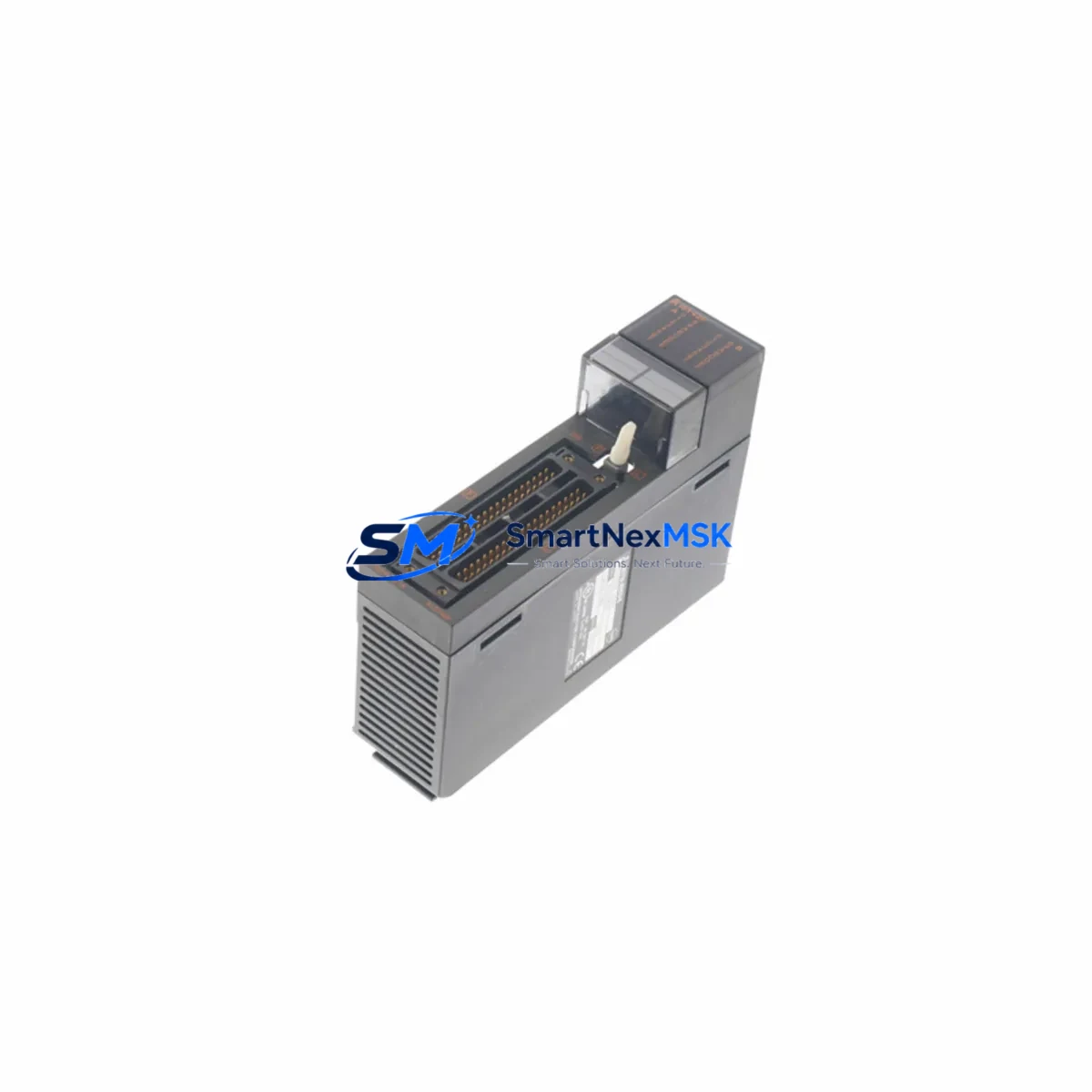
This listing provides an original Mitsubishi Electric A1SY42P output module, sourced from authorized supply channels, inspected prior to dispatch, and backed by a 12-month warranty. Each unit undergoes functional verification before shipment to ensure it meets the electrical and signal integrity specifications required for direct installation into MELSEC-A base units.
Spare Maintenance Table
| Parameter | Specification |
|---|---|
| Model / SKU | A1SY42P |
| Brand | Mitsubishi Electric |
| Series | MELSEC-A (A1S Series) |
| Module Type | Transistor Output Module (Sink) |
| Output Points | 32 Points |
| Output Voltage | 12–24 VDC |
| Max Load Current | 0.1 A per point / 4 A per common |
| Isolation Method | Photocoupler |
| Response Time | 1 ms or less (OFF→ON / ON→OFF) |
| Connector Type | 40-pin connector |
| Compatible Base Units | A1S Series main base / extension base |
| Operating Temperature | 0°C to 55°C |
| Storage Temperature | -25°C to 75°C |
| Origin | Japan |
| Condition | Original / New-Old-Stock / Tested |
| Warranty | 12 Months |
| Shipping | Tested & Fast Dispatch |
Maintenance Planning for Continuous Operation
When replacing the A1SY42P in a MELSEC-A control cabinet, a thorough maintenance inspection of the surrounding electrical circuit is essential to prevent repeat failures and ensure long-term system stability. Maintenance engineers should treat this replacement as an opportunity to audit the full output loop.
Begin by inspecting the A1S power supply module (such as the A1S61PN or A1S62PN) — an aging or under-rated power supply is a common root cause of output module degradation. Verify that the DC bus voltage is within specification under load before installing the new A1SY42P. Next, check the A1SCPU or A2SCPU central processing unit for any latched fault codes or watchdog errors that may have contributed to the output module failure.
Inspect the terminal block wiring and I/O connector for signs of oxidation, loose crimps, or insulation damage — particularly on high-cycle output channels driving solenoid valves or motor contactors. If the system uses an A1SX40 or A1SX80 input module in the same base, verify that input signal integrity has not been compromised by ground loops or common-mode noise.
For systems with relay-driven loads, check the condition of any intermediate relay modules or relay terminal boards connected downstream of the A1SY42P. Relay coil inrush and back-EMF can stress transistor output stages over time; installing surge suppression diodes or RC snubber circuits at the load terminals is a recommended preventive measure.
If the control cabinet includes a MELSEC-A communication module such as the A1SJ71UC24-R2 or A1SJ71AP23Q, verify that the network link is stable and that no communication timeout errors are logged — these can mask output module faults during diagnostics. For systems with signal isolators or analog I/O modules (e.g., A1S68AD or A1S62DA), confirm that analog reference signals remain within calibrated range after the output module swap.
Finally, review the fuse holders and circuit protection on the output commons. A blown common fuse is frequently overlooked during emergency replacements and will prevent the new module from functioning correctly. Stocking a set of replacement fuses alongside the A1SY42P is a best practice for any MELSEC-A spare parts kit.
Site Replacement Workflow
Step 1 — Safety Isolation: De-energize the control cabinet and lock out / tag out (LOTO) the power supply. Confirm zero voltage on the DC bus before proceeding.
Step 2 — Fault Documentation: Record all active and latched fault codes from the CPU module. Photograph the existing wiring and connector orientation before disconnection.
Step 3 — Module Removal: Disconnect the 40-pin I/O connector from the A1SY42P. Release the module locking tab and slide the unit out of the base slot. Note the slot number for reinstallation.
Step 4 — Compatibility Verification: Confirm that the replacement A1SY42P matches the original module’s output type (sink transistor), voltage rating, and point count. Cross-reference the base unit slot assignment in the PLC parameter settings.
Step 5 — Installation: Insert the new A1SY42P into the correct base slot until the locking tab engages. Reconnect the 40-pin connector, ensuring all pins are fully seated. Restore power and observe the module’s RUN/ERR LED indicators.
Step 6 — Functional Test: Force-ON each output point via the CPU’s diagnostic function or programming tool (GX Developer / GX Works2) and verify actuator response. Clear all latched faults and return the system to automatic operation.
This workflow minimizes downtime by eliminating guesswork during the replacement process. The A1SY42P is a direct plug-in replacement for the original module — no parameter changes or hardware modifications are required when replacing a like-for-like unit in the same base slot.
Spare Parts Support FAQ
Q1: Is the A1SY42P still available as a new original part?
The MELSEC-A series has reached end-of-life status with Mitsubishi Electric, but original A1SY42P units remain available through authorized industrial spare parts suppliers. Each unit we supply is inspected and tested prior to shipment. We maintain stock of key MELSEC-A modules to support legacy system maintenance and life extension programs.
Q2: How do I verify compatibility before installation?
The A1SY42P is compatible with all A1S series main base units and extension bases that support standard output modules. Verify the slot type in your base unit hardware manual and confirm that your CPU parameter settings assign the correct module type to the target slot. If you are migrating from an older A-series base to an A1S-series base, consult the MELSEC-A hardware compatibility guide or contact our technical team with your system configuration.
Q3: What pre-shipment testing is performed on each unit?
Every A1SY42P is powered up and subjected to output point functional verification before dispatch. We check for correct LED indication, output switching response, and isolation integrity. Units that do not pass testing are not shipped. A test report is available upon request for critical maintenance applications.
Q4: What does the 12-month warranty cover?
The 12-month warranty covers manufacturing defects and functional failures under normal operating conditions. It does not cover damage caused by incorrect installation, overvoltage, reverse polarity, or physical impact. In the event of a warranty claim, we provide a replacement unit or full refund after fault verification. Long-term supply agreements and consignment stock arrangements are available for customers with ongoing MELSEC-A maintenance programs.
© 2026 SMARTNEXMSK. All rights reserved.
Original Source: https://smartnexmsk.com
Contact: sales@smartnexmsk.com | +86 18259474341


