Mitsubishi A2USHCPU-S1 Retrofit-Ready CPU for MELSEC-A Control Systems: Compatible Modernization & Smooth Legacy Upgrade
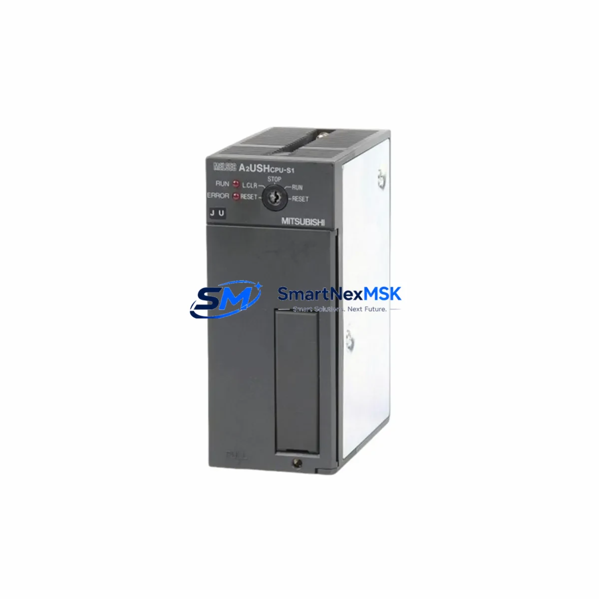
The Mitsubishi Electric A2USHCPU-S1 is a high-performance CPU module designed for the MELSEC-A Series programmable logic controller platform. As legacy MELSEC-A installations approach end-of-life and original A2USHCPU-S1 units become increasingly difficult to source through standard distribution channels, this module serves as the definitive retrofit-ready solution for engineers managing aging control infrastructure across manufacturing, utilities, and process automation environments.
Whether you are replacing a failed unit on an active production line, upgrading a control cabinet as part of a planned modernization program, or sourcing a verified spare to protect against unplanned downtime, the A2USHCPU-S1 delivers the exact electrical, mechanical, and software compatibility required for seamless integration into existing MELSEC-A rack assemblies. The module slots directly into A-Series base units including the A38B, A68B, and A98B backplanes without requiring structural modification to the control cabinet or changes to the existing terminal wiring layout.
Upgrade Compatibility Table
| Parameter | Detail |
|---|---|
| SKU / Part Number | A2USHCPU-S1 |
| Series Compatibility | Mitsubishi MELSEC-A Series (A2U, A3U, A2US, A2USH platform) |
| Replaces / Supersedes | A2UCPU, A2UCPU-S1, A2USCPU, A2USHCPU (earlier revisions) |
| Backplane / Rack Interface | Compatible with A38B, A68B, A98B base units; standard A-Series bus connector |
| Power Supply Requirement | Supplied by rack-mounted PSU (A61P, A62P, A63P compatible); verify PSU capacity before installation |
| Communication Ports | RS-422 programming port; compatible with A6GPP, A7PHP programming panels and GX Developer / GX Works2 via SC-09 or USB-SC09-A cable |
| I/O Point Capacity | Up to 2048 I/O points (with extension base units) |
| Program Memory | 60K steps (with memory cassette); supports ladder, SFC, and structured text |
| Communication Protocol Compatibility | MELSEC-A dedicated protocol; compatible with A1SJ71UC24-R2, A1SJ71E71-B2 Ethernet and serial communication modules |
| Retrofit Recommendation | Direct slot replacement; re-upload existing GX Developer project; verify I/O module addresses and special function module parameters |
| Commissioning Focus | Module address assignment, watchdog timer settings, data register initialization, HMI screen tag re-mapping |
| Warranty | 12 Months — covers manufacturing defects and functional failure under normal operating conditions |
Retrofit Planning for Existing Automation Systems
A successful A2USHCPU-S1 retrofit begins well before the replacement unit arrives on site. Engineers should start by auditing the existing rack assembly to confirm the installed base unit model, the slot position of the current CPU, and the total power draw of all installed modules. The rack-mounted power supply — typically an A61P or A62P unit — must have sufficient headroom to support the A2USHCPU-S1 alongside any co-installed I/O modules such as the A1SX40, A1SY10, or A1SX80 digital input/output modules, as well as any analog modules like the A68AD or A62DA that may be present in the same chassis.
Terminal wiring on the I/O modules does not need to be disturbed during a CPU swap, which significantly reduces retrofit risk. However, engineers should photograph and document all terminal assignments and verify that the existing wiring labels match the current I/O map in the GX Developer project file before proceeding. If the control system includes special function modules such as the A1SD75P1-S3 positioning module or the A1SJ71UC24-R2 serial communication module, the module start addresses and parameter settings stored in those units must be verified against the CPU’s FROM/TO instruction logic after the new CPU is installed.
For systems that include an A8GT-GOT or GT1155-QSBD HMI panel communicating with the CPU over RS-422, the communication parameters — baud rate, station number, and protocol format — must be confirmed to match the settings configured in the replacement A2USHCPU-S1. In most cases, these settings are retained in the HMI project file and do not require modification, but a communication link test should be performed as part of the commissioning checklist before returning the line to production.
Where the existing system uses an A1SJ71E71-B2 Ethernet module for SCADA connectivity or remote monitoring, engineers should verify that the CPU’s network parameter table correctly references the Ethernet module’s slot position and IP configuration. This is particularly important when the replacement CPU is initialized from a backup project file rather than a live read from the original unit.
Memory cassettes — such as the A3NMCA-8 or A2NMCA-16 — should be inspected and re-seated during the retrofit. If the original CPU’s program was stored on a memory cassette rather than internal RAM, the cassette can be transferred directly to the replacement A2USHCPU-S1, provided the cassette type is compatible with the module’s memory interface. Always verify the program checksum after transfer using GX Developer’s verify function before energizing the system.
Downtime Control During System Migration
Minimizing production downtime during a CPU replacement requires a structured pre-outage preparation protocol. Before scheduling the maintenance window, the engineering team should perform a full online read of the existing CPU using GX Developer or GX Works2 to capture the current ladder program, device comments, parameter settings, and any active data register values that form part of the process recipe or batch control logic. This backup should be stored in at least two locations — a local engineering workstation and a network share — and the file timestamp should be verified before the outage begins.
During the outage, the sequence should follow a defined order: de-energize the rack, remove the failed or end-of-life A2USHCPU-S1, install the replacement module, re-energize the rack, and perform a cold write of the backed-up project file before enabling outputs. The entire CPU swap can typically be completed within 15 to 30 minutes by a trained automation technician, with the remaining commissioning time — typically 30 to 60 minutes — spent on communication link verification, HMI screen validation, and a supervised dry-run of the control sequence with outputs inhibited.
For critical processes where even a brief interruption is unacceptable, consider staging the replacement CPU in a bench test environment using a spare A38B base unit and a programming cable such as the USB-SC09-A to pre-load and verify the program before the scheduled outage. This approach allows the commissioning team to confirm program integrity, module addressing, and communication parameters in advance, reducing the live outage window to the minimum time required for the physical swap and final I/O verification.
After the replacement is complete and the system has been returned to automatic mode, the control logic should be monitored for a minimum of one full production cycle before the maintenance team stands down. Any deviations in output timing, counter values, or communication response times should be investigated and resolved before the system is handed back to operations.
Retrofit Support FAQ
Q1: Is the A2USHCPU-S1 a direct drop-in replacement for the A2USHCPU and A2UCPU-S1?
Yes. The A2USHCPU-S1 is mechanically and electrically compatible with the A2USHCPU and A2UCPU-S1 in the same rack slot. The module uses the same A-Series backplane bus connector and is recognized by GX Developer and GX Works2 without requiring changes to the project hardware configuration in most standard retrofit scenarios. Verify the CPU type setting in the project parameters matches the installed module before writing the program.
Q2: What programming cable and software are required for commissioning?
The A2USHCPU-S1 uses an RS-422 programming port. The recommended interface cable is the USB-SC09-A (USB to RS-422 converter), which is compatible with GX Developer version 8.x and GX Works2. Older SC-09 serial cables can also be used with a PC equipped with a native RS-232 port or a USB-to-serial adapter. Ensure the COM port settings in GX Developer match the cable driver configuration before attempting to connect.
Q3: How do I verify wiring and I/O compatibility before powering up the replacement module?
Before energizing the rack, confirm that all I/O module terminal wiring is intact and that the I/O module types and slot positions match the hardware configuration defined in the CPU project file. Use a multimeter to verify that the power supply output voltage is within specification (typically 5 VDC ±5% on the backplane bus). Check that any special function modules — such as positioning or communication modules — are seated correctly and that their rotary address switches match the module start addresses referenced in the CPU program.
Q4: What does the 12-month warranty cover, and what is the process for a warranty claim?
The 12-month warranty covers manufacturing defects and functional failures under normal operating conditions, including CPU processing faults, memory errors, and communication port failures that are not attributable to external damage, incorrect installation, or overvoltage events. To initiate a warranty claim, contact sales@smartnexmsk.com with the order reference number, a description of the fault symptom, and photographs of the installed module and any visible damage. Replacement or repair will be arranged within the warranty period at no additional cost to the buyer.
© 2026 SMARTNEXMSK. All rights reserved.
Original Source: https://smartnexmsk.com
Contact: sales@smartnexmsk.com | +86 18259474341


