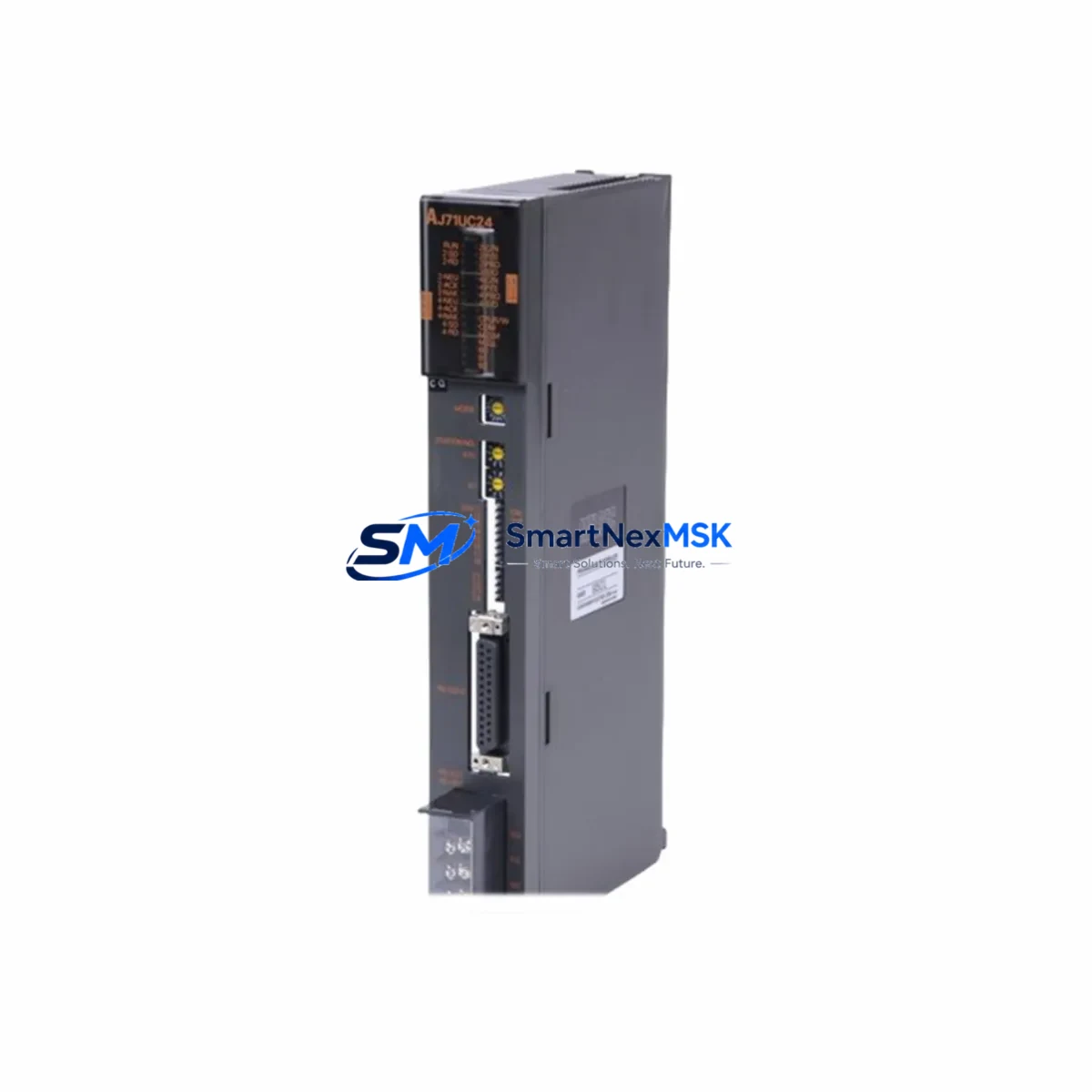
Mitsubishi AJ71UC24 Retrofit-Ready CC-Link Master for MELSEC-A Control Systems
The Mitsubishi AJ71UC24 is a CC-Link master communication module originally designed for the MELSEC-A series programmable logic controller platform. As MELSEC-A series hardware reaches end-of-life and spare parts become increasingly scarce, the AJ71UC24 has become one of the most sought-after retrofit and replacement components for engineers tasked with modernizing legacy control cabinets without full system overhauls. Our inventory is sourced, inspected, and tested to ensure drop-in compatibility with existing MELSEC-A backplane configurations, delivering a reliable upgrade path that minimizes engineering risk and unplanned downtime.
Whether you are replacing a failed unit on an active production line, building a spare-parts buffer for a critical facility, or executing a phased migration from MELSEC-A to MELSEC-Q or MELSEC-iQ-R architecture, the AJ71UC24 serves as the communication backbone that keeps your CC-Link network operational. Its master-station role allows it to manage up to 64 remote I/O stations, coordinating data exchange across distributed field devices including remote terminal units, intelligent device stations, and local stations — all without requiring changes to the upstream CPU ladder logic when used as a direct replacement.
Upgrade Compatibility Table
| Parameter | AJ71UC24 (This Module) | Retrofit Notes |
|---|---|---|
| Network Type | CC-Link Ver. 1.10 | Compatible with CC-Link Ver. 1.00 slave devices; verify baud rate settings on all remote stations |
| Installation Slot | MELSEC-A main base / extension base | Fits A1S, A2S, A3N, A2N, A1N series base units; confirm slot count and power budget before installation |
| Power Consumption | 5 VDC, 0.54 A (internal bus) | Verify remaining capacity on A1S61PN, A1S62PN, or A62P power supply modules before adding to rack |
| Communication Speed | 156 kbps / 625 kbps / 2.5 Mbps / 5 Mbps / 10 Mbps | Match baud rate to existing CC-Link cable topology and total network length; re-terminate if cable is extended |
| Max Remote Stations | 64 stations | Audit existing station address assignments before replacement to avoid address conflicts |
| Terminal Wiring | DA, DB, DG, SLD, FG screw terminals | Reuse existing CC-Link cable; confirm shield grounding at one end only per CC-Link wiring standard |
| CPU Compatibility | A1CPU, A2CPU, A3CPU, A1SCPU, A2SCPU series | No ladder program changes required for direct replacement; verify FROM/TO instruction addresses if module slot changes |
| Replacement Path | Replaces: AJ71UC24, AJ71C24, AJ71C24-S3 | For migration to MELSEC-Q: use QJ61BT11N with A-to-Q conversion base adapter |
| Commissioning Check | LED indicators: RUN, ERR, L RUN, L ERR, SD, RD | Confirm all remote station L RUN LEDs illuminate within 5 seconds of power-on; check ERR LED for station address faults |
| Warranty | 12-Month Warranty — covers functional defects under normal operating conditions. Includes pre-shipment power-on test and burn-in verification. | |
Retrofit Planning for Existing Automation Systems
A successful AJ71UC24 retrofit begins well before the module arrives on site. The first step is a full audit of the existing MELSEC-A rack configuration. Document every module installed in the main base and any extension bases connected via the A1SC09B or A1SC12B extension cables. Record the slot number of the original AJ71UC24 or its predecessor, because the CPU references the module by slot address in FROM/TO buffer memory instructions. If the replacement module occupies the same physical slot, no program changes are required. If the slot changes — for example, because a failed backplane forces a rack reconfiguration — the GX Developer or GX Works2 project file must be updated to reflect the new I/O assignment before the system is restarted.
Power budget verification is a frequently overlooked step that causes commissioning delays. The A1S62PN power supply module, commonly found in A1S-series cabinets, provides 3 A on the 5 VDC internal bus. Adding or replacing communication modules can push the rack close to its power limit, particularly in densely populated configurations that already include analog I/O modules such as the A68AD or A62DA, high-speed counter modules, or positioning modules. Calculate the total 5 VDC draw for all installed modules and confirm at least 10% headroom remains after the AJ71UC24 is installed.
On the CC-Link network side, inspect the existing field wiring before powering up. The AJ71UC24 uses a three-wire shielded twisted-pair cable (DA, DB, DG) with terminating resistors at both ends of the trunk line. If the original cable has been in service for more than five years in an industrial environment, check for insulation degradation, loose terminal screws, and shield continuity. Remote I/O stations such as the AJ65SBTB1-16D input module and AJ65SBTB1-16T transistor output module should be powered down during the master module swap to prevent spurious output signals during the initialization sequence. After the AJ71UC24 is seated and powered, bring remote stations online one group at a time, monitoring the L RUN and L ERR LEDs on each station to confirm clean network enumeration.
For sites planning a longer-term migration from MELSEC-A to MELSEC-Q, the AJ71UC24 can serve as a bridge-phase component. The QJ61BT11N CC-Link master module for the MELSEC-Q platform is fully compatible with the same CC-Link Ver. 1.10 slave devices, meaning the field wiring, remote I/O stations, and intelligent device stations do not need to change during the CPU platform upgrade. The migration sequence typically involves installing a MELSEC-Q rack alongside the existing MELSEC-A cabinet, connecting both systems via the A1SJ71QLP21 MELSEC-NET/10 link module or a direct data-sharing arrangement, and running parallel operation for a validation period before cutting over. During this phase, the AJ71UC24 continues to manage the CC-Link network while the new Q-series CPU is commissioned and the ladder program is converted using GX Works2’s A-to-Q conversion utility.
HMI integration is another critical checkpoint. If the existing control cabinet uses a GOT1000 series HMI panel connected to the MELSEC-A CPU via RS-232 or the A-bus, verify that the GOT screen project references the correct device addresses. A direct module replacement does not affect CPU device memory, so HMI screens that read and write M, D, and Y devices will continue to function without modification. However, if the retrofit involves any change to the CC-Link station assignments or buffer memory mapping, the GOT project must be reviewed to ensure that any direct CC-Link buffer reads are updated accordingly. Programming cables such as the SC-09 RS-232 programming cable remain compatible with the A-series CPU throughout the retrofit process, allowing on-site program verification without additional hardware investment.
Downtime Control During System Migration
Minimizing production downtime during a CC-Link master module replacement requires a structured pre-outage preparation protocol. Before scheduling the maintenance window, obtain a verified backup of the CPU program using GX Developer or GX Works2 connected via the SC-09 programming cable. Store the backup on at least two separate media — a local engineering laptop and a network file server — and confirm the backup reads back correctly before proceeding. Document the current state of all output devices: valve positions, motor run/stop status, conveyor states, and any interlocks that must be manually held during the outage to prevent equipment damage or safety incidents.
The physical module swap on a MELSEC-A rack is a hot-swap-prohibited operation. The entire rack must be de-energized before removing or inserting any module. Plan the outage window to include: rack power-down (2 minutes), module removal and replacement (5 minutes), visual inspection of backplane connector pins (3 minutes), rack power-up and network initialization (5 minutes), and a functional verification sequence covering all CC-Link remote stations (15–30 minutes depending on network size). A total window of 45–60 minutes is realistic for a single-rack replacement with a pre-tested module.
To protect original program logic, never overwrite the CPU memory during the commissioning phase. Use the GX Developer “Monitor” mode to observe CC-Link buffer memory (BFM) values in real time as remote stations come online. Compare the live BFM data against the pre-outage baseline values recorded during the preparation phase. If any remote station fails to enumerate — indicated by a persistent L ERR LED — isolate that station’s cable segment and verify terminal resistance before suspecting a station hardware fault. In most cases, CC-Link enumeration failures after a master module replacement are caused by terminating resistor omission or a loose DA/DB terminal screw rather than a defective remote station.
For facilities that cannot tolerate extended outages, consider pre-staging a tested AJ71UC24 with all rotary switches pre-set to match the original module’s station count and baud rate configuration. This reduces the in-cabinet commissioning time to the physical swap and power-cycle sequence, with network initialization completing automatically based on the pre-configured switch settings. All units shipped from our inventory are pre-tested under power with CC-Link loopback verification before dispatch, reducing the risk of receiving a non-functional module during a time-critical maintenance event.
Retrofit Support FAQ
Q1: Is the AJ71UC24 a direct drop-in replacement for the AJ71C24 and AJ71C24-S3?
Yes. The AJ71UC24 is the designated replacement for both the AJ71C24 and AJ71C24-S3 in MELSEC-A racks. The module occupies the same slot footprint, uses the same backplane connector, and is recognized by the same CPU I/O assignment. No ladder program changes are required when replacing in the same slot position. Verify that the rotary switches for station count and baud rate are set identically to the original module before powering up.
Q2: What wiring changes are needed when installing the AJ71UC24?
No wiring changes are required for a direct replacement. Reconnect the existing CC-Link trunk cable to the DA, DB, and DG terminals in the same polarity as the original module. Confirm that the shield (SLD) terminal is connected at the master end and that terminating resistors (110 Ω for Ver. 1.10 at speeds above 156 kbps) are present at both ends of the trunk. If the cable has been extended or rerouted since the original installation, re-verify total cable length against the CC-Link distance specification for the selected baud rate.
Q3: How do I verify compatibility with my existing CC-Link slave devices?
The AJ71UC24 supports CC-Link Ver. 1.10 and is backward compatible with Ver. 1.00 slave devices. Collect the model numbers of all remote stations on your network — including remote I/O, intelligent device stations, and local stations — and confirm their CC-Link version from the device manual or nameplate. Any Ver. 1.00 or Ver. 1.10 slave device will communicate correctly with the AJ71UC24 master. Ver. 2.00 extended cyclic devices are not supported and would require a QJ61BT11N master on a MELSEC-Q platform.
Q4: What does the 12-month warranty cover, and what pre-shipment testing is performed?
Every AJ71UC24 unit undergoes a pre-shipment power-on test that verifies the RUN LED illuminates, the CC-Link network initializes correctly in loopback mode, and all diagnostic LEDs respond as specified. The 12-month warranty covers functional defects arising under normal operating conditions — correct supply voltage, ambient temperature within specification, and proper installation per the MELSEC-A hardware manual. Physical damage caused by incorrect installation, overvoltage, or environmental contamination is excluded. Warranty claims are processed with a replacement-first policy to minimize your downtime exposure.
© 2026 SMARTNEXMSK. All rights reserved.
Original Source: https://smartnexmsk.com
Contact: sales@smartnexmsk.com | +86 18259474341


