Mitsubishi AY13 Maintenance-Ready Spare for MELSEC-A Automation
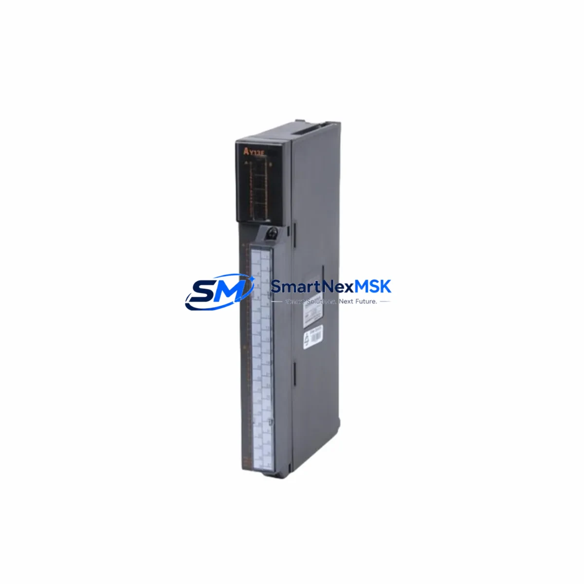
The Mitsubishi AY13 is a 16-point NPN transistor output module designed for the MELSEC-A series programmable logic controller platform. As a genuine original spare part, the AY13 is a critical component in industrial control cabinets where reliable digital output switching is essential for motor drives, solenoid valves, indicator lamps, and relay coil actuation. For maintenance engineers managing aging MELSEC-A systems, securing a verified AY13 spare is the single most effective measure to minimize unplanned downtime and restore production continuity within the shortest possible window.
Whether you are executing a planned shutdown inspection, responding to an emergency fault, or building a strategic spare parts inventory for a legacy automation system, the AY13 represents a high-priority line item. Its NPN open-collector output architecture is directly compatible with the MELSEC-A backplane bus, and its 16-point density makes it a versatile replacement across a wide range of machine control and process automation applications throughout manufacturing, automotive, food processing, and utilities sectors.
Spare Maintenance Table
| Parameter | Specification / Detail |
|---|---|
| SKU / Part Number | AY13 |
| Brand | Mitsubishi Electric |
| Series | MELSEC-A |
| Module Type | Digital Output Module (Transistor NPN) |
| Output Points | 16 Points |
| Output Type | NPN Open Collector (Sink) |
| Rated Load Voltage | 12–24 VDC |
| Max Load Current | 0.1 A per point |
| Isolation Method | Photocoupler |
| Backplane Compatibility | MELSEC-A Series Base Units |
| Installation | Direct slot insertion, MELSEC-A rack mount |
| Operating Temperature | 0°C to 55°C |
| Storage Temperature | -25°C to 75°C |
| Origin | Japan |
| Condition | Original, New or Tested Surplus |
| Pre-shipment Testing | Function verified before dispatch |
| Warranty | 12 Months |
| Maintenance Recommendation | Inspect output transistor status, wiring terminals, and LED indicators during each scheduled cabinet inspection. Replace proactively if output response time degrades or point failures exceed 2 per module. |
Maintenance Planning for Continuous Operation
When replacing the AY13 in a MELSEC-A control system, a thorough maintenance engineer will treat the module swap as an opportunity to audit the surrounding electrical environment. The AY13 does not operate in isolation — its performance depends on the integrity of the entire output circuit and the health of adjacent components within the same control cabinet.
Begin by verifying the A1S61PN or A1S62PN power supply module output voltage stability. A degraded power supply is a common root cause of intermittent output module faults and can cause premature failure of a newly installed AY13. Next, inspect the A1SCPU or A2SCPU CPU module for any active error codes or watchdog faults that may have triggered the output module failure in the first place.
Check the terminal block wiring and screw torque on the AY13’s 40-pin connector. Loose terminals are a leading cause of output point failure in high-vibration environments. If the cabinet also contains an AX40 or AX80 digital input module, inspect those simultaneously — input and output modules in the same I/O loop often experience correlated wear patterns.
For systems using A1SJ71UC24-R2 or A1SJ71UC24-R4 serial communication modules, confirm that the communication link to the host SCADA or HMI remains stable after the module replacement, as backplane reseating can occasionally reset communication parameters. If the system includes an A985GOT or A975GOT HMI panel, verify that the screen correctly reflects the restored output status after the AY13 is brought online.
In cabinets where signal isolators or relay output expansion units are used downstream of the AY13, test each relay coil actuation individually before returning the system to automatic mode. Pay particular attention to any fuse holders or miniature circuit breakers protecting the 24 VDC output commons — a blown fuse on the common line will disable an entire group of output points and is frequently misdiagnosed as a module fault. Finally, if the system uses an A1SD51S positioning module or pulse output card in the same rack, confirm that the rack’s total current draw remains within the base unit’s rated capacity after the AY13 is installed.
Site Replacement Workflow
Step 1 — Safe Isolation: Place the MELSEC-A CPU in STOP mode via the RUN/STOP key switch or from the programming console. De-energize the output field devices connected to the AY13 before removing the module to prevent arc damage to the backplane connector.
Step 2 — Module Removal: Release the module locking lever, pull the AY13 straight out of the slot, and inspect the backplane connector pins for corrosion or mechanical damage. Clean with isopropyl alcohol if necessary before installing the replacement unit.
Step 3 — Replacement Installation: Insert the new AY13 into the same slot position. The MELSEC-A platform does not require parameter changes for a like-for-like module replacement — the CPU will automatically recognize the module on the next power cycle. No re-programming is required.
Step 4 — Power-Up and Verification: Restore power, switch the CPU to RUN mode, and observe the AY13’s output LEDs. Force each output point ON individually from the programming tool (GX Developer or GX Works2) to confirm all 16 points are functional before releasing the system to production.
Step 5 — Documentation: Record the replacement date, module serial number, and test results in the equipment maintenance log. Update the spare parts inventory to trigger a replenishment order for the next AY13 unit, ensuring continuous spare coverage.
This workflow minimizes mean time to repair (MTTR) and ensures the system is returned to full operational status with confidence, without the risk of latent faults caused by incomplete verification.
Spare Parts Support FAQ
Q1: Is the AY13 still available as a new original part, or only as tested surplus?
The AY13 is a legacy MELSEC-A series module that Mitsubishi Electric has transitioned to end-of-life status. We source verified original units from authorized industrial surplus channels and subject each unit to functional output testing before shipment. All units are supplied with a 12-month warranty covering manufacturing defects and functional failures under normal operating conditions.
Q2: How do I confirm the AY13 is compatible with my specific MELSEC-A base unit?
The AY13 is compatible with all standard MELSEC-A series base units, including the A1S33B, A1S38B, A1S65B, and A1S68B rack configurations. Compatibility is determined by the backplane bus standard, not the specific rack size. If you are unsure, provide your base unit model number and CPU type and our technical team will confirm compatibility before shipment.
Q3: What is your recommended spare parts stocking strategy for MELSEC-A systems?
For production-critical MELSEC-A installations, we recommend maintaining a minimum of one AY13 spare per active system, with a two-unit buffer for facilities operating multiple MELSEC-A racks. Given the end-of-life status of the platform, proactive stocking is strongly advised — market availability of legacy MELSEC-A modules tightens progressively each year. Pairing your AY13 stock with a spare CPU module and power supply unit provides comprehensive coverage for the most common failure scenarios.
Q4: What pre-shipment testing does each AY13 unit undergo?
Every AY13 unit is powered up and subjected to point-by-point output switching tests across all 16 channels prior to packaging. We verify LED indicator function, output transistor switching response, and photocoupler isolation integrity. Units that fail any test parameter are quarantined and not shipped. A test record is available upon request, and all shipped units are covered by our 12-month replacement warranty.
© 2026 SMARTNEXMSK. All rights reserved.
Original Source: https://smartnexmsk.com
Contact: sales@smartnexmsk.com | +86 18259474341


