Mitsubishi AY13E Retrofit-Ready Output Module for MELSEC-A Control Systems
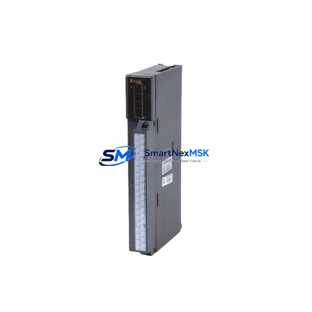
The Mitsubishi Electric AY13E is a 32-point transistor (sink) digital output module engineered for the MELSEC-A Series programmable logic controller platform. As legacy MELSEC-A installations approach end-of-life and original AY13E units become increasingly difficult to source through standard distribution channels, this module remains a critical component for engineers managing retrofit projects, spare-parts inventories, and control-cabinet upgrades across manufacturing, utilities, and process-automation environments.
Whether you are replacing a failed output card in a running production line, migrating a legacy A2SCPU or A3NCPU-based system to a modernized architecture, or simply maintaining a strategic buffer stock of discontinued Mitsubishi modules, the AY13E delivers the electrical and logical compatibility required to restore full system operation with minimal engineering rework.
Upgrade Compatibility Table
| Parameter | AY13E Specification | Retrofit Notes |
|---|---|---|
| Output Points | 32 points (transistor sink) | Direct replacement for AY13, AY13A; verify load current per point |
| Rated Load Voltage | 12–24 VDC | Confirm field device voltage before wiring; no relay buffer required for 24 VDC loads |
| Max Load Current | 0.1 A/point, 2 A/common | Derate for high-cycle solenoid or inductive loads; add flyback diodes if absent |
| Backplane Interface | MELSEC-A bus connector | Compatible with A1S, A2S, A3N, A2N base units; verify slot assignment in GX Developer |
| Module Address | Set via base unit slot position | Re-map I/O addresses in ladder program if slot position changes during retrofit |
| Communication Protocol | MELSEC-A internal bus | No protocol change required; for CC-Link migration, pair with AJ65SBTB1-16DT |
| Installation | DIN-rail or panel-mount base unit | No mechanical modification to cabinet required; module slides into existing slot |
| Programming Tool | GX Developer / GX Works2 | Existing ladder programs are fully reusable; no re-compilation needed for same-slot replacement |
| Warranty | 12 Months | Covers manufacturing defects; includes pre-shipment functional test report |
Retrofit Planning for Existing Automation Systems
A successful AY13E retrofit begins well before the module arrives on-site. Engineers should start by auditing the existing MELSEC-A base unit — whether an A1S, A2S, or A3N chassis — to confirm available slot count, total power budget, and backplane bus integrity. The A1S61PN or A1S62PN power supply module must be verified to supply sufficient current for the expanded I/O load; adding a 32-point output card to a near-capacity rack can push the 5 VDC internal bus beyond its rated output, causing intermittent faults or unexpected CPU resets.
Terminal wiring is the next critical checkpoint. The AY13E uses a 40-pin connector with a standard MELSEC-A pinout. If the original module was an AY13 or AY13A, the field wiring harness can typically be transferred directly. However, if the retrofit involves replacing an older relay-output module such as the AY22 or AY23, engineers must account for the change from dry-contact to transistor-sink outputs — field devices expecting a voltage-free contact will require an interposing relay or a solid-state relay (SSR) buffer stage.
For systems where the MELSEC-A CPU — such as the A2SCPU or A3NCPU — is also being replaced as part of a broader platform migration toward the MELSEC-Q or MELSEC-iQ-R series, the AY13E can serve as a transitional output module during a phased cutover. In this scenario, the new Q02CPU or R04CPU controller is installed in a parallel rack while the legacy A-Series rack continues to handle field I/O. The AY13E remains active on the old rack, maintaining output control until the new I/O modules — such as the QY10 or RY10R2 transistor output cards — are fully wired, addressed, and verified in the new program.
Communication link integrity must also be assessed. If the existing system uses an A1SJ71UC24-R4 serial communication module for SCADA or HMI connectivity, confirm that the HMI screen tags referencing output coil addresses remain valid after any slot reassignment. MELSEC-A I/O addresses are slot-position-dependent; moving the AY13E to a different slot without updating the GX Developer I/O assignment table will cause address conflicts and may trigger CPU error codes E1 or E6.
Downtime Control During System Migration
Minimizing unplanned downtime is the primary engineering constraint in any MELSEC-A retrofit. The recommended approach is a hot-standby swap strategy: pre-configure and bench-test the replacement AY13E before the scheduled maintenance window. Use GX Developer to export the current I/O parameter file and verify that the module type registered in the base unit configuration matches the AY13E. If the original module entry is listed as AY13 or AY13A, update the I/O assignment to AY13E and perform an offline simulation to confirm no address conflicts exist.
During the physical swap, power down only the affected rack segment if the system uses a multi-rack configuration with an A1SB37 or A1SB70 extension base unit. This allows other racks — and their associated I/O, including analog input modules such as the A68AD — to remain powered and in scan mode, preserving process data and reducing the scope of the shutdown. After inserting the AY13E, restore power and perform a forced-output test from GX Developer’s device monitor to verify each of the 32 output points before releasing the system to automatic mode.
For sites where zero-unplanned-downtime is a contractual requirement, a pre-shipment functional test report is available for each AY13E unit. This document confirms point-by-point output switching, leakage current measurement, and response-time verification — providing the documentation trail required for ISO 9001 maintenance records and customer acceptance sign-off.
Retrofit Support FAQ
Q1: Is the AY13E a direct drop-in replacement for the AY13 and AY13A?
Yes. The AY13E is electrically and mechanically compatible with the AY13 and AY13A in the same MELSEC-A base unit slot. The connector pinout, I/O point count, and bus interface are identical. No ladder program changes are required if the module occupies the same slot position. Confirm load voltage and current ratings match your field devices before installation.
Q2: What pre-shipment testing is performed on each AY13E unit?
Each module undergoes a full functional test prior to dispatch: all 32 output points are switched under rated load, leakage current is measured at rated voltage, and response time is verified against Mitsubishi Electric specifications. A test report is available upon request and is included with orders requiring quality documentation for maintenance records.
Q3: Can the AY13E be used during a phased migration from MELSEC-A to MELSEC-Q?
Yes. The AY13E can remain active on the legacy A-Series rack during a parallel-rack migration. It continues to drive field outputs while the new Q-Series or iQ-R rack is commissioned. Once the new output modules — such as the QY10 or RY10R2 — are verified and the program cutover is complete, the AY13E rack can be decommissioned in a controlled shutdown without affecting the new system.
Q4: What is the warranty coverage and what does it include?
All AY13E units supplied by SMARTNEXMSK carry a 12-month warranty covering manufacturing defects and functional failures under normal operating conditions. The warranty period begins from the date of shipment. In the event of a warranty claim, we provide advance replacement to minimize production downtime, subject to fault verification. Contact sales@smartnexmsk.com with your order reference and fault description to initiate a claim.
© 2026 SMARTNEXMSK. All rights reserved.
Original Source: https://smartnexmsk.com
Contact: sales@smartnexmsk.com | +86 18259474341


