Mitsubishi AY40 Retrofit-Ready PLC Output for MELSEC-A Control Systems
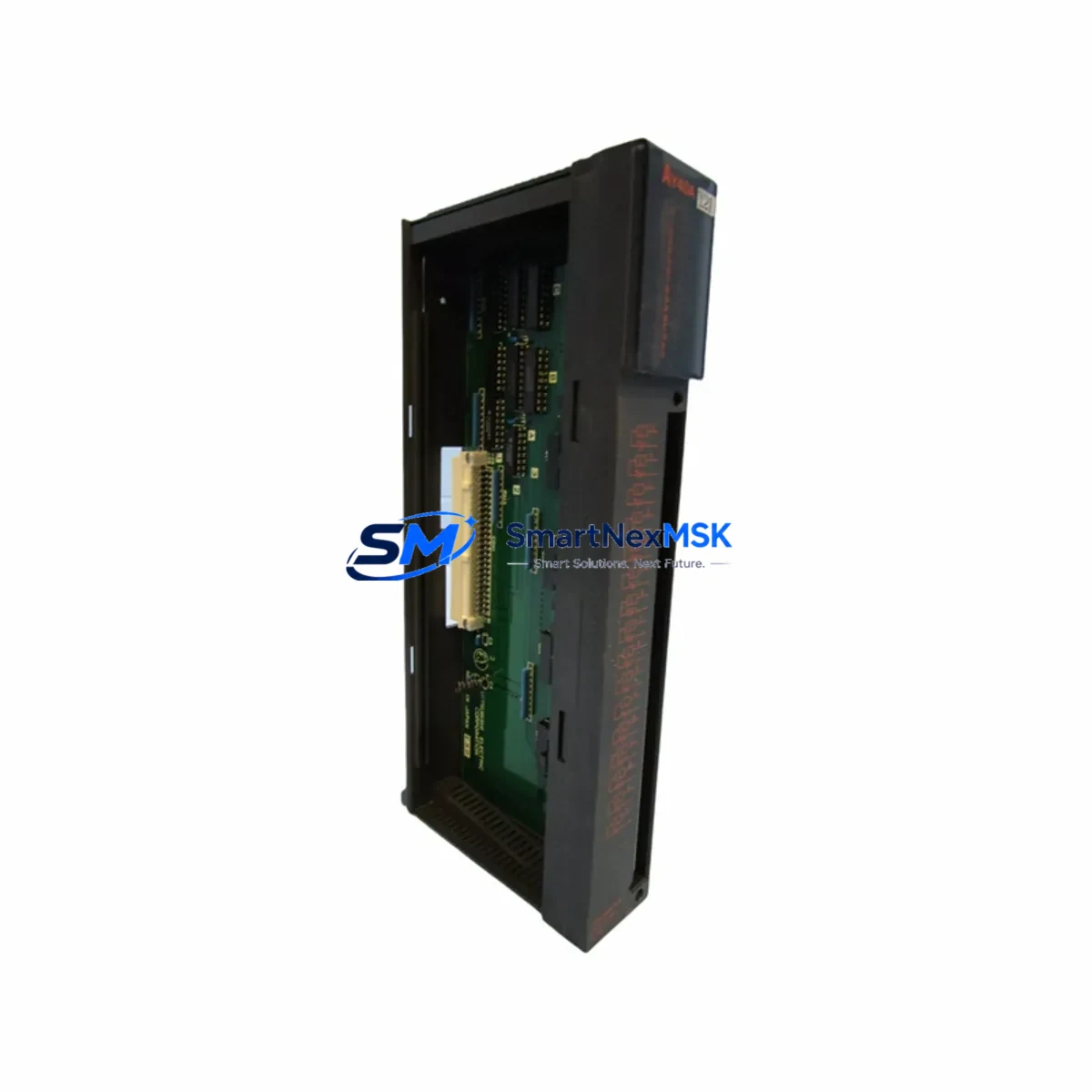
The Mitsubishi Electric AY40 is a 32-point transistor output module engineered for the MELSEC-A Series programmable logic controller platform. As legacy MELSEC-A installations approach end-of-life or require capacity expansion, the AY40 remains one of the most sought-after retrofit and replacement components in the Mitsubishi automation ecosystem. Whether you are restoring a failed output module on a running production line, upgrading an aging control cabinet, or migrating I/O architecture to extend system life, the AY40 delivers the electrical compatibility, mechanical fit, and signal integrity that retrofit engineers demand.
The AY40 provides 32 transistor (NPN sink) output points organized across dual 16-point groups, with a rated load voltage of 12–24 VDC and a maximum load current of 0.1 A per point. Its compact A-series form factor slots directly into standard MELSEC-A base units — including the A1S series main base and extension base units — without mechanical modification. Terminal block wiring follows the original AY40 pinout, meaning field wiring from existing actuators, solenoid valves, relay coils, and indicator lamps can be reconnected without rewiring the cabinet. This direct wiring compatibility is critical for minimizing downtime during unplanned module replacement in continuous-process environments.
Before committing to an AY40 retrofit, engineers should verify several key parameters. First, confirm that the host base unit — typically an A1S series or A2S series main base — has sufficient available slot capacity and that the power supply module (such as the A1S61PN or A1S62PN) can support the additional output load current. Second, review the GX Developer or GX Works2 program to confirm that the output module’s X/Y device address assignments match the physical slot position in the base unit; incorrect address mapping will cause output misfire or program faults at startup. Third, inspect the terminal block connector for pin corrosion or mechanical damage before reusing field wiring from the legacy module.
For sites migrating from older A-series hardware to a modernized control architecture, the AY40 can serve as a transitional I/O module while the main CPU — such as an A2USCPU or A3UCPU — is retained during a phased upgrade. In mixed-generation cabinets where an A1SJ71QLP21 MELSECNET/10 communication module or an A1SJ71UC24-R4 serial communication module is already installed, the AY40 integrates without protocol changes, preserving the existing network topology and HMI screen tag assignments. This is particularly valuable when the SCADA or GOT series HMI (such as a GOT1000 or GOT2000 panel) is configured with fixed device addresses tied to the original I/O layout.
In control cabinets where the AY40 operates alongside analog output modules such as the A68DAV or A616DAI, engineers must account for shared power rail loading. The 24 VDC field power supply feeding the AY40 output commons should be sized to handle simultaneous activation of all 32 output points under worst-case load conditions. A dedicated 24 VDC switching power supply with adequate current headroom — separate from the CPU and communication module supply — is recommended practice for high-density output configurations.
For sites where the original AY40 has failed due to output transistor burnout from inductive load switching, it is advisable to install flyback diodes or RC snubber circuits on inductive loads (solenoids, relay coils) before commissioning the replacement module. This protective measure extends module service life and reduces the risk of repeat failures in harsh industrial environments. Surge suppression components should be verified on all output circuits before the replacement module is powered.
SMARTNEXMSK maintains verified stock of the Mitsubishi AY40 and related MELSEC-A series components. Every unit undergoes pre-shipment functional testing to confirm output switching performance, terminal integrity, and module identification. Supply continuity is supported for long-term MRO procurement, with a 12-month warranty covering manufacturing defects and functional failures under normal operating conditions. Fast dispatch is available for urgent replacement orders requiring minimal production downtime.
Upgrade Compatibility Table
| Parameter | Specification / Retrofit Guidance |
|---|---|
| SKU / Model | AY40 |
| Brand / Series | Mitsubishi Electric / MELSEC-A Series |
| Output Type | Transistor (NPN Sink), 32 Points |
| Rated Load Voltage | 12–24 VDC |
| Max Load Current | 0.1 A per point / 1.6 A per common |
| Compatible Base Units | A1S Main Base, A2S Extension Base, A-Series Slim Base |
| Slot Interface | A-Series backplane connector (direct drop-in) |
| Terminal Block | 40-pin screw terminal, original pinout retained |
| Compatible CPUs | A1SCPU, A2USCPU, A3UCPU, A1SHCPU |
| Communication Compatibility | MELSECNET/10, RS-232C, RS-422 (via existing comm modules) |
| Programming Software | GX Developer, GX Works2 (A-series mode) |
| Replacement Verification | Confirm Y-device address, power rail load, terminal wiring |
| Commissioning Notes | Verify output commons, check inductive load suppression |
| Origin | Japan |
| Warranty | 12-Month Warranty — Functional defects covered from shipment date |
Retrofit Planning for Existing Automation Systems
A successful AY40 retrofit begins with a thorough audit of the existing control cabinet. In a typical MELSEC-A installation, the cabinet houses an A1S series main base unit carrying the CPU module, power supply, and a mix of digital and analog I/O modules. The AY40 occupies one slot in this base, and its replacement requires the cabinet to be de-energized — or, where hot-swap procedures are documented — carefully isolated before module extraction.
Engineers should document the existing terminal block wiring before disconnecting the legacy AY40. Photograph or sketch the field wiring connections at the 40-pin terminal block, noting wire colors, circuit labels, and common terminal groupings. This documentation accelerates reconnection and reduces the risk of wiring errors when the replacement module is installed. If the original terminal block connector is damaged or corroded, a replacement terminal block compatible with the AY40 footprint should be sourced alongside the module.
In cabinets where the AY40 operates alongside an A1SJ71QLP21 MELSECNET/10 communication module, verify that the network station number and module parameters stored in the CPU program are not affected by the slot change. If the AY40 is being relocated to a different slot position during the retrofit — for example, to accommodate a new A68DAV analog output module — the GX Developer program must be updated to reflect the new Y-device address mapping before the system is restarted.
For sites upgrading from a legacy A2USCPU to a newer Q-series or iQ-R series controller as part of a broader modernization project, the AY40 may be retained as a transitional output module during the migration phase. Mitsubishi’s A/QnA conversion adapter (AX40S or equivalent) can facilitate mechanical and electrical compatibility between A-series I/O modules and Q-series base units in some configurations, extending the useful life of existing field wiring and reducing rewiring costs. The A1S62PN power supply module should be evaluated for continued use or replacement with a Q-series equivalent during this transition.
HMI screens on GOT1000 or GOT2000 panels connected to the MELSEC-A CPU via RS-232C or MELSECNET should be reviewed for device address dependencies. Output coils mapped to the AY40’s Y-device range must remain consistent after the retrofit to avoid HMI display errors or incorrect operator feedback. Where the HMI project file is available, a pre-retrofit simulation using GT Designer3 can validate screen behavior before the physical changeover.
Programming cables such as the SC-09 RS-232C cable or USB-SC09-FX adapter are required for online monitoring and program verification during commissioning. After the AY40 replacement is installed and wired, connect the programming device, switch the CPU to MONITOR mode, and force-test each output point individually to confirm correct field device response before returning the system to AUTO mode.
Downtime Control During System Migration
Minimizing production downtime during an AY40 replacement or MELSEC-A system migration requires advance preparation and a structured changeover sequence. The most effective approach is to pre-stage the replacement AY40 module, verify its functional test report, and prepare all tools, terminal documentation, and programming equipment before the maintenance window begins.
Where the production schedule permits a planned shutdown, coordinate the AY40 replacement with other scheduled maintenance tasks — such as power supply inspection, terminal block cleaning, or communication cable replacement — to consolidate downtime into a single window. For unplanned failures, SMARTNEXMSK’s in-stock availability and fast dispatch capability support same-day or next-day shipment to minimize the gap between failure and restoration.
During the changeover, retain the original AY40 as a reference unit until the replacement has been fully commissioned and verified. If the original module has partially failed (some output points functional, others not), it can be used to cross-check terminal wiring and device address assignments during the transition. Once the replacement module is confirmed operational across all 32 output points, the original unit can be returned for warranty evaluation or disposed of per site procedures.
For sites with redundant control architectures — where a standby CPU or backup I/O rack is available — the AY40 replacement can be performed without a full production stop by switching control to the standby system during the module swap. This approach requires pre-verified program synchronization between the primary and standby CPUs and should be tested during a scheduled maintenance window before being relied upon for emergency changeovers.
After commissioning, document the retrofit in the site’s maintenance log, including the replacement module’s serial number, installation date, slot position, and any wiring modifications made during the changeover. This record supports future troubleshooting, warranty claims, and procurement planning for long-term spare parts management.
Retrofit Support FAQ
Q1: Is the AY40 a direct drop-in replacement for a failed MELSEC-A output module?
Yes. The AY40 is mechanically and electrically compatible with the original MELSEC-A series base unit slot. The 40-pin terminal block pinout is retained, so existing field wiring can be reconnected without modification. Confirm the Y-device address assignment in the CPU program matches the physical slot position before restarting the system.
Q2: What pre-shipment testing is performed on AY40 units?
Every AY40 unit supplied by SMARTNEXMSK undergoes functional output switching tests across all 32 points, terminal block integrity checks, and module identification verification before dispatch. A test report is available upon request. Units are shipped in anti-static packaging to prevent ESD damage during transit.
Q3: Can the AY40 be used in a Q-series or iQ-R series base unit during a migration project?
The AY40 is natively designed for MELSEC-A series base units. Direct installation into Q-series or iQ-R series base units is not supported without a conversion adapter. For migration projects, consult Mitsubishi’s A/QnA conversion documentation or contact SMARTNEXMSK for guidance on compatible transition hardware.
Q4: What does the 12-month warranty cover?
The 12-month warranty covers manufacturing defects and functional failures under normal operating conditions from the shipment date. It includes free replacement or repair for confirmed defective units. The warranty does not cover damage caused by incorrect installation, overvoltage, reverse polarity, or physical mishandling. SMARTNEXMSK supports long-term supply continuity for AY40 and related MELSEC-A components to meet ongoing MRO and retrofit procurement needs.
© 2026 SMARTNEXMSK. All rights reserved.
Original Source: https://smartnexmsk.com
Contact: sales@smartnexmsk.com | +86 18259474341


