Mitsubishi FX2N-16EX-ES/UL Maintenance-Ready Spare FX2N: Spare Replacement & Industrial Downtime Risk Control
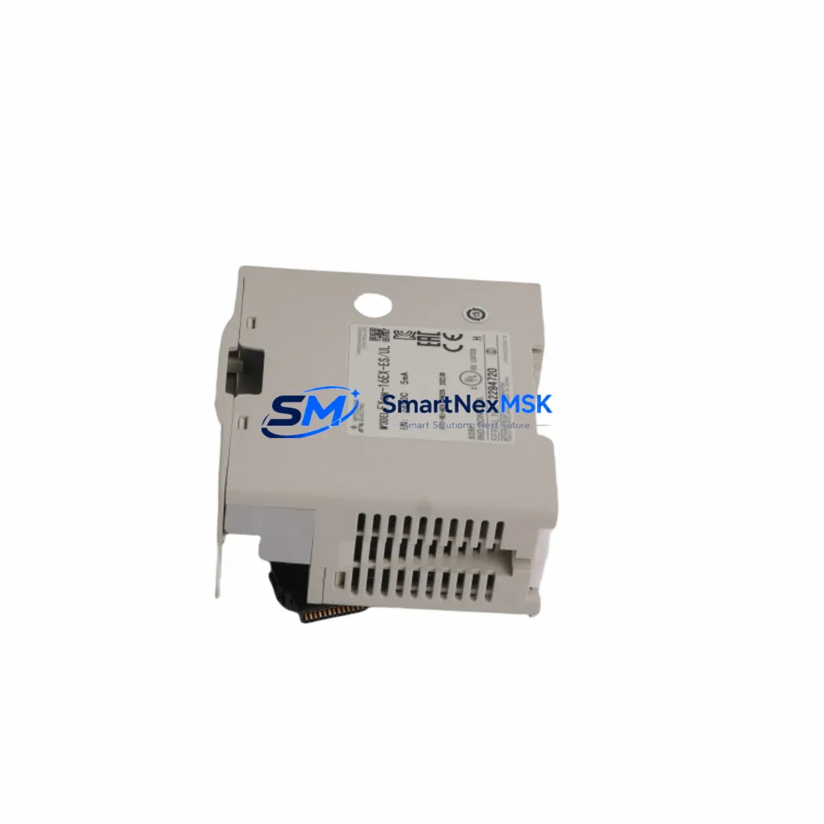
The Mitsubishi FX2N-16EX-ES/UL is a 16-point DC digital input extension module designed for the Mitsubishi FX2N Series programmable logic controller platform. As a critical I/O expansion component in distributed control cabinets, field panel assemblies, and legacy automation systems, this module plays a central role in maintaining uninterrupted process monitoring across manufacturing, packaging, material handling, and discrete production lines. Sourced as an original Mitsubishi Electric spare part, the FX2N-16EX-ES/UL is tested prior to shipment and backed by a 12-month warranty, making it a reliable choice for both planned maintenance schedules and emergency replacement scenarios.
For maintenance engineers managing aging FX2N-based control systems, having a verified spare of the FX2N-16EX-ES/UL on hand is a fundamental element of any downtime prevention strategy. When this module fails or degrades, the associated input signals — proximity sensors, limit switches, pushbuttons, and field device feedback — are lost, potentially halting an entire production cell. Fast replacement with a pre-tested original module restores system integrity without requiring PLC reprogramming or hardware reconfiguration, provided the replacement unit matches the original’s wiring and I/O addressing.
Spare Maintenance Table
| Parameter | Specification |
|---|---|
| Model / SKU | FX2N-16EX-ES/UL |
| Brand | Mitsubishi Electric |
| Series | FX2N |
| Module Type | Digital Input Extension Module |
| Number of Input Points | 16 points (DC input) |
| Input Voltage | 24V DC (sink/source compatible) |
| Input Current | Approx. 7 mA per point |
| Isolation Method | Photocoupler isolation |
| Compatibility | Mitsubishi FX2N, FX2NC Series PLC |
| Connection Method | Terminal block (M3 screws) |
| Operating Temperature | 0°C to 55°C |
| Storage Temperature | -25°C to 75°C |
| Humidity | 5% to 95% RH (non-condensing) |
| Origin | Japan |
| Certification | UL Listed (ES/UL variant) |
| Installation | DIN rail or direct panel mount via FX2N expansion bus |
| Warranty | 12 Months |
| Condition | Original, tested before shipment |
Maintenance Planning for Continuous Operation
When scheduling a replacement of the FX2N-16EX-ES/UL, experienced maintenance and procurement engineers know that a single module swap rarely tells the full story of a control cabinet’s health. A thorough inspection of the surrounding system components is essential to prevent repeat failures and ensure long-term operational stability.
Begin by verifying the FX2N Series power supply module — typically the FX2N-1PS-5V or the main CPU’s integrated power section — to confirm that the 24V DC supply rail feeding the extension module is within tolerance. Voltage sags or ripple on the DC bus are a common root cause of intermittent input faults that are misdiagnosed as module failure. Alongside the power supply, inspect the FX2N-16EYR or FX2N-16EYT output extension modules installed in the same cabinet; output modules sharing the same expansion bus are subject to the same environmental stresses and may show early signs of relay contact wear or transistor degradation.
Check the FX2N-32MT or FX2N-48MT CPU module for firmware integrity and scan time anomalies, as an overloaded CPU can mask genuine I/O faults. If the system uses FX2N-232-BD or FX2N-485-BD communication boards for SCADA or HMI connectivity, verify that serial communication parameters remain stable after the module replacement — a loose expansion connector can disrupt both I/O and communication simultaneously.
For cabinets with signal conditioning requirements, inspect any installed signal isolators or loop-powered transmitter barriers connected to the input terminals. Degraded isolation can introduce ground loops that corrupt digital input readings. Also review the terminal blocks and wiring ferrules at the module’s input connector; oxidized or loose terminations are a frequent source of intermittent faults in high-vibration environments. Replace any suspect fuse holders or miniature circuit breakers protecting the 24V input circuit at the same time.
If the system includes an FX2N-4AD analog input module or FX2N-2DA analog output module on the same expansion bus, confirm that the bus connector seating is secure after reinstalling the digital input module. Finally, if an GOT1000 or GOT2000 Series HMI is connected to the FX2N CPU, perform a communication test post-replacement to confirm that all monitored I/O addresses are correctly reflected on the operator panel before returning the system to production.
Site Replacement Workflow
Replacing the FX2N-16EX-ES/UL on-site is a straightforward procedure when the correct spare is available and the replacement is properly verified before installation. Follow this workflow to minimize downtime and maintain system compatibility:
1. Pre-Replacement Verification: Confirm the replacement unit’s model number matches exactly — FX2N-16EX-ES/UL — including the ES/UL certification suffix, which indicates UL listing compliance. Do not substitute with FX2N-16EX (non-UL) variants in UL-certified panel installations without engineering approval.
2. Safe Isolation: De-energize the control cabinet following your site’s lockout/tagout (LOTO) procedure. Disconnect the 24V DC supply to the extension module before removing the terminal block wiring. Photograph or document the existing wiring layout before disconnection.
3. Module Removal: Disconnect the FX2N expansion bus connector between the CPU (or preceding extension module) and the FX2N-16EX-ES/UL. Remove the module from the DIN rail or panel mount. Inspect the bus connector pins for damage or corrosion.
4. Installation: Mount the replacement FX2N-16EX-ES/UL and reconnect the expansion bus connector. Reconnect all input wiring per the documented layout. Torque terminal screws to the specified value (typically 0.5–0.8 N·m) to prevent loose connections.
5. Power-Up and Functional Test: Re-energize the system and monitor the PLC’s I/O status display or connected HMI for correct input state readings. Activate each field device connected to the 16 input points to verify end-to-end signal integrity before releasing the system to production.
This workflow applies equally to planned maintenance replacements and emergency downtime recovery scenarios. Keeping a pre-tested FX2N-16EX-ES/UL spare in your local inventory eliminates procurement lead time from the critical path of any unplanned outage.
Spare Parts Support FAQ
Q1: Is the FX2N-16EX-ES/UL compatible with both FX2N and FX2NC Series PLCs?
The FX2N-16EX-ES/UL is designed for the FX2N Series expansion bus. Compatibility with FX2NC requires an FX2NC-CNV-IF conversion adapter, as the FX2NC uses a compact connector format. Always verify the expansion bus connector type before ordering for FX2NC applications.
Q2: What does the 12-month warranty cover, and how is it validated?
The 12-month warranty covers manufacturing defects and functional failures under normal operating conditions. Each unit is tested for input response, isolation integrity, and bus communication before shipment. Warranty claims are supported with proof of purchase and a fault description. Units damaged by incorrect wiring, overvoltage, or environmental exposure beyond specification are not covered.
Q3: How should I manage FX2N-16EX-ES/UL inventory for a multi-line facility?
For facilities operating multiple FX2N-based lines, a minimum stock of one spare per four installed modules is a practical baseline. High-criticality lines — where a single I/O fault causes full production stoppage — warrant a dedicated on-shelf spare. Rotate stock annually and verify stored units with a bench test before committing them to emergency use.
Q4: Can the FX2N-16EX-ES/UL replace older or discontinued FX2N input extension variants?
The FX2N-16EX-ES/UL is the current UL-listed variant of the FX2N 16-point DC input extension module and is a direct functional replacement for earlier FX2N-16EX units in most applications. Confirm I/O address mapping in the PLC program and verify that the input wiring polarity (sink vs. source) matches your field device configuration before finalizing the replacement.
© 2026 SMARTNEXMSK. All rights reserved.
Original Source: https://smartnexmsk.com
Contact: sales@smartnexmsk.com | +86 18259474341


