Mitsubishi FX2NC-16EX Spare for FX2NC Automation: Spare Replacement & Industrial Downtime Risk Control
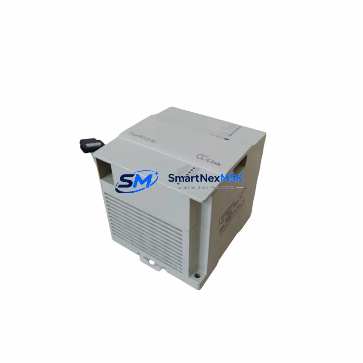
The Mitsubishi FX2NC-16EX is a 16-point digital input extension module designed for the MELSEC FX2NC series compact PLC platform. As a maintenance-ready original spare, the FX2NC-16EX is a critical component in control cabinets across discrete manufacturing, material handling, packaging lines, and process automation systems. When this module fails or degrades, the entire I/O subsystem can be compromised, leading to unplanned downtime and production loss. Stocking a verified replacement unit is the most effective strategy for rapid fault recovery and system continuity.
This listing provides an original, tested FX2NC-16EX sourced for industrial maintenance and spare parts procurement. Each unit undergoes pre-shipment functional verification and is backed by a 12-month warranty, ensuring confidence for both planned overhauls and emergency replacements.
Spare Maintenance Table
| Parameter | Specification |
|---|---|
| Model / SKU | FX2NC-16EX |
| Brand | Mitsubishi Electric |
| Series | MELSEC FX2NC |
| Module Type | Digital Input Extension Module |
| Number of Input Points | 16 points (sink/source selectable) |
| Input Voltage | 24 VDC |
| Input Current | Approx. 5 mA per point |
| Isolation Method | Photocoupler |
| Connector Type | Compact connector (FX2NC bus) |
| Compatibility | FX2NC-32MT, FX2NC-64MT, FX2NC-96MT and FX2NC series CPUs |
| Operating Temperature | 0°C to 55°C |
| Storage Temperature | -25°C to 75°C |
| Humidity | 5% to 95% RH (non-condensing) |
| Installation | DIN rail or direct mount via FX2NC bus connector |
| Origin | Japan |
| Condition | Original, pre-shipment tested |
| Warranty | 12 Months |
Maintenance Planning for Continuous Operation
When a maintenance or procurement engineer identifies the FX2NC-16EX as a fault point or scheduled replacement target, the inspection scope should extend beyond the module itself. A thorough control cabinet audit at the time of replacement significantly reduces the risk of repeat failures and secondary faults.
Begin by verifying the 24 VDC power supply feeding the FX2NC expansion bus — a degraded or undersized power supply unit is a common root cause of intermittent input faults that are incorrectly attributed to the I/O module. Inspect the FX2NC-32MT or FX2NC-64MT CPU module for firmware integrity and bus communication health before reconnecting the replacement unit.
Check all terminal blocks and field wiring connected to the 16 input points. Loose terminals, corroded contacts, or undersized conductors can cause false input signals that damage replacement modules prematurely. If the system uses intermediate relays or solid-state relays to interface field sensors with PLC inputs, inspect relay coil resistance and contact wear — these components often fail silently alongside aging I/O modules.
For systems with signal isolators between field instruments and the FX2NC-16EX input channels, verify isolation barrier integrity and output signal levels. Degraded isolators can inject noise or incorrect voltage levels that stress input optocouplers. Review the FX2NC-CNV-IF conversion adapter if the system bridges FX2N and FX2NC bus segments — connector wear at this interface is a frequent but overlooked failure point.
If the control cabinet includes a GOT1000 or GOT2000 series HMI communicating with the FX2NC CPU, confirm that the communication cable and RS-422 or USB interface remain intact after module replacement. Also inspect fuse holders and miniature circuit breakers protecting the 24 VDC input circuit — a blown fuse is often the first indicator of a field wiring short that caused the original module failure.
For aging systems, consider proactively replacing the FX2NC-16EYT output extension module alongside the input module if both are of similar age and duty cycle. Pairing input and output module replacements during a single planned maintenance window minimizes future downtime exposure and reduces repeat cabinet access.
Site Replacement Workflow
Step 1 — Isolation & Lockout: De-energize the control cabinet and apply LOTO (Lockout/Tagout) procedures. Confirm 24 VDC bus voltage is zero before disconnecting the FX2NC-16EX.
Step 2 — Documentation: Photograph or record the existing wiring layout, terminal assignments, and I/O address mapping from the PLC program (GX Developer or GX Works2) before removal. The FX2NC-16EX occupies a fixed I/O address block determined by its position on the expansion bus — confirm the replacement unit is installed in the identical bus slot position.
Step 3 — Module Removal: Disconnect the compact bus connector carefully. Avoid bending the connector pins. Remove field wiring terminal connections and label each wire if not already documented.
Step 4 — Replacement Installation: Install the new FX2NC-16EX in the same bus position. Reconnect field wiring per the original terminal layout. Ensure the bus connector is fully seated and latched.
Step 5 — Power-Up & Verification: Restore 24 VDC power. Monitor the CPU module’s RUN/ERROR LED status. Use GX Developer or GX Works2 to perform an online I/O monitor check — verify all 16 input points respond correctly to field signals before returning the system to production.
Step 6 — Compatibility Note: The FX2NC-16EX is not directly interchangeable with FX2N-16EX (standard FX2N series) due to the compact bus connector design. Confirm the replacement SKU matches the installed series before ordering. This unit is confirmed compatible with all FX2NC series CPU modules.
Spare Parts Support FAQ
Q1: Is this FX2NC-16EX an original Mitsubishi Electric component?
Yes. All units are original Mitsubishi Electric FX2NC-16EX modules. Each unit is pre-shipment tested for functional integrity and ships with a 12-month warranty covering manufacturing defects and operational failures under normal industrial use conditions.
Q2: Can the FX2NC-16EX replace an FX2N-16EX in an existing installation?
No. The FX2NC-16EX uses a compact bus connector specific to the FX2NC series and is not physically or electrically compatible with the standard FX2N expansion bus. Ensure your CPU module is an FX2NC series unit before ordering. If you are operating an FX2N series system, the correct replacement is the FX2N-16EX.
Q3: What is the recommended spare parts stocking strategy for FX2NC I/O modules?
For production-critical systems, we recommend maintaining at least one FX2NC-16EX and one FX2NC-16EYT (output module) as on-hand cold spares. For multi-cabinet installations or systems with 3+ FX2NC expansion modules, a ratio of one spare per five installed modules is a practical minimum. Long lead times on legacy MELSEC components make proactive stocking essential for minimizing downtime exposure.
Q4: How is the unit tested before shipment?
Each FX2NC-16EX undergoes a functional power-on test verifying input channel response, bus communication integrity, and LED indicator operation. Units that do not pass all test criteria are not shipped. Test records are available upon request for quality-critical procurement processes.
© 2026 SMARTNEXMSK. All rights reserved.
Original Source: https://smartnexmsk.com
Contact: sales@smartnexmsk.com | +86 18259474341


