Mitsubishi FX3U-80MR/ES Maintenance-Ready Spare for FX3U Automation
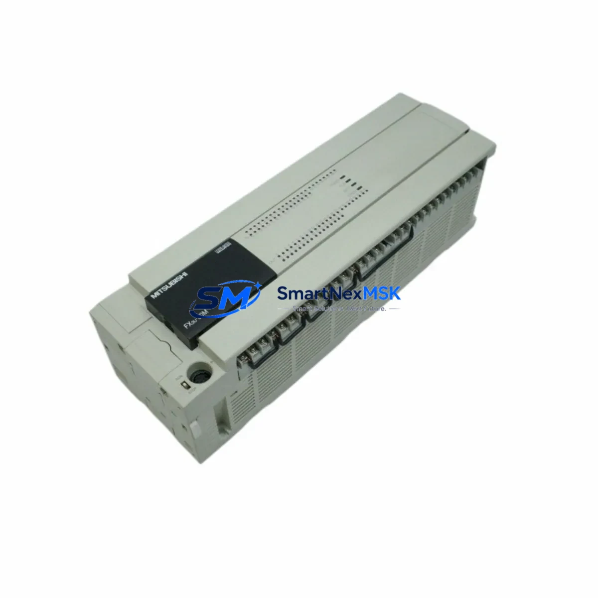
When a Mitsubishi FX3U-80MR/ES fails on the production floor, every minute of unplanned downtime translates directly into lost output and escalating recovery costs. The FX3U-80MR/ES is an 80-point relay output PLC main unit operating on AC power supply (100–240 V AC), belonging to Mitsubishi Electric’s FX3U series — one of the most widely deployed compact PLC platforms in discrete manufacturing, material handling, packaging, and process control across Asia-Pacific and global industrial facilities. Sourced as an original Mitsubishi Electric component, this spare unit is pre-tested, serialized, and dispatched with a 12-month warranty, enabling maintenance teams to execute a verified swap and restore system operation with minimal interruption.
For maintenance engineers managing aging FX3U-based control systems, holding a certified spare FX3U-80MR/ES in the on-site spare parts cabinet is the single most effective strategy for reducing mean time to repair (MTTR). For procurement engineers, sourcing this unit from a specialist industrial automation supplier — with documented compatibility confirmation, pre-shipment testing records, and long-term supply continuity — eliminates the risk of counterfeit components and ensures traceability throughout the asset lifecycle.
Spare Maintenance Table
| Parameter | Specification |
|---|---|
| SKU / Part Number | FX3U-80MR/ES |
| Brand | Mitsubishi Electric |
| Series | FX3U |
| Product Type | Programmable Logic Controller (PLC) Main Unit |
| I/O Points | 80 points (40 inputs / 40 outputs) |
| Output Type | Relay (MR) |
| Power Supply | AC 100–240 V, 50/60 Hz |
| Origin | Japan |
| Compatibility | FX3U series expansion modules, FX3U-CNV-BD, FX3U-232-BD, FX3U-485-BD, FX3U-USB-BD |
| Communication | RS-422 (built-in), optional RS-232/RS-485/USB via BD board |
| Max Extension | Up to 256 I/O points with expansion modules |
| Programming Software | GX Works2, GX Developer |
| Operating Temperature | 0–55 °C |
| Mounting | DIN rail or direct screw mount |
| Maintenance Recommendation | Replace battery (FX3U-32BL) every 5 years; inspect terminal blocks annually |
| Pre-Shipment Testing | Power-on, I/O verification, communication port check |
| Warranty | 12 Months |
Maintenance Planning for Continuous Operation
A disciplined maintenance plan for any FX3U-80MR/ES installation extends well beyond the PLC main unit itself. During scheduled control cabinet inspections or emergency fault isolation, maintenance engineers should systematically evaluate all components sharing the same electrical circuit and communication backbone.
Begin with the FX3U-1PSU-5V auxiliary power supply unit if the cabinet includes high-density I/O expansion — an unstable 5 V rail is a common root cause of intermittent I/O faults that are incorrectly attributed to the PLC CPU. Inspect the FX3U-16EX or FX3U-32EX input expansion modules for loose terminal connections and verify that 24 V DC input signal levels are within specification. On the output side, relay contact wear on the FX3U-80MR/ES itself should be assessed against the rated switching cycles; if output relay contacts show signs of arcing or contact resistance increase, companion FX3U-16EYR relay output extension modules in the same cabinet should be inspected simultaneously.
Communication integrity is equally critical. If the system uses an FX3U-485-BD or FX3U-232-BD communication board for SCADA, HMI, or inverter connectivity, verify termination resistors, cable shielding continuity, and connector seating. For installations using an FX3U-USB-BD for local programming access, confirm the board is firmly seated and the USB driver is current. Where the FX3U-80MR/ES interfaces with an F940GOT or GT2107 series HMI panel, validate the communication parameters (baud rate, station number, protocol) match the replacement unit’s configuration before going live.
Terminal block integrity across the I/O wiring — particularly TBC series screw terminal blocks and ferrule-terminated conductors — should be torque-checked during any planned maintenance window. Signal isolators such as the MTL5000 series or equivalent DIN-rail isolators protecting analog input channels should be tested for drift. Fuse holders and miniature circuit breakers (MCBs) protecting the 24 V DC auxiliary supply and AC input circuits must be verified for correct rating and continuity. Finally, if the FX3U-80MR/ES is part of a networked CC-Link or MELSECNET system, the FX3U-16CCL-M CC-Link master module should be inspected for communication error flags before and after the PLC replacement to confirm network integrity is maintained.
Site Replacement Workflow
Replacing an FX3U-80MR/ES in a live industrial environment requires a structured approach to minimize downtime and eliminate configuration errors. Follow this sequence for a safe, efficient swap:
- Backup the program: Using GX Works2 or GX Developer, read and save the current ladder program, device comments, and parameter settings to a local PC before powering down. Confirm the backup file is complete and readable.
- Document I/O wiring: Photograph or sketch the terminal block wiring layout. Label all I/O cables if not already tagged. Note the positions of any BD communication boards installed on the existing unit.
- Power down safely: Isolate the AC supply to the PLC cabinet via the main isolator. Verify zero voltage at the PLC power terminals with a calibrated multimeter before touching any wiring.
- Remove the faulty unit: Disconnect all I/O terminal blocks, power terminals, and the BD board (if fitted). Release the DIN rail locking tab and slide the unit free.
- Install the replacement FX3U-80MR/ES: Mount the new unit on the DIN rail, reconnect all terminal blocks in the documented order, and reinstall the BD communication board. Verify all connections are torqued to specification.
- Restore the program: Power on the unit and use GX Works2 to write the backed-up program and parameters to the new PLC. Set the real-time clock if required.
- Verify operation: Run a forced I/O test to confirm all 40 inputs and 40 relay outputs respond correctly. Check communication links to HMI and any networked devices. Confirm no error LEDs are active before returning the system to automatic operation.
This workflow is equally applicable when upgrading from an older FX2N-80MR or FX1N-60MR to the FX3U-80MR/ES, where the expanded memory, built-in high-speed counters, and enhanced communication options of the FX3U platform deliver a meaningful improvement in system capability and long-term supportability.
Spare Parts Support FAQ
Q1: What is the expected service life of the FX3U-80MR/ES, and when should I plan a proactive replacement?
Mitsubishi Electric rates the FX3U series for a design life of approximately 10 years under standard industrial operating conditions. In practice, relay output contacts have a mechanical life of around 10 million operations and an electrical life dependent on load type and switching frequency. For systems operating in high-cycle applications, proactive replacement at 7–8 years — or upon first detection of relay contact degradation — is recommended. Holding a certified spare in your on-site inventory eliminates lead-time risk when the replacement decision is made.
Q2: How do I confirm compatibility between the replacement FX3U-80MR/ES and my existing expansion modules and BD boards?
The FX3U-80MR/ES is fully compatible with all FX3U series expansion I/O modules (FX3U-16EX, FX3U-32EX, FX3U-16EYR, etc.) and all FX3U-xBD communication boards. Compatibility with FX2N expansion modules is also supported via the FX3U-CNV-BD adapter. Before installation, verify that the firmware version of the replacement unit is equal to or newer than the original; if a program was developed on a specific firmware version, confirm there are no known compatibility notes in the Mitsubishi release history for your program features.
Q3: What pre-shipment testing is performed, and what documentation is provided?
Every FX3U-80MR/ES unit undergoes power-on verification, full I/O point cycling, communication port functional check, and visual inspection for physical integrity prior to dispatch. Units are shipped in anti-static packaging with original labeling intact. A test record is available upon request. The 12-month warranty covers manufacturing defects and functional failures under normal operating conditions from the date of receipt.
Q4: Can you support long-term or blanket purchase orders for ongoing spare parts inventory programs?
Yes. For maintenance teams managing multiple FX3U-based systems or operating under a planned preventive maintenance (PPM) schedule, we support standing purchase orders, scheduled release orders, and consignment stock arrangements. Long-term supply continuity for the FX3U-80MR/ES and associated components — including FX3U expansion modules, BD boards, and battery units — is available. Contact our technical sales team to discuss your inventory strategy and volume requirements.
© 2026 SMARTNEXMSK. All rights reserved.
Original Source: https://smartnexmsk.com
Contact: sales@smartnexmsk.com | +86 18259474341


