Mitsubishi GX41N Retrofit-Ready DC Input Module for MELSEC-Q Control Systems
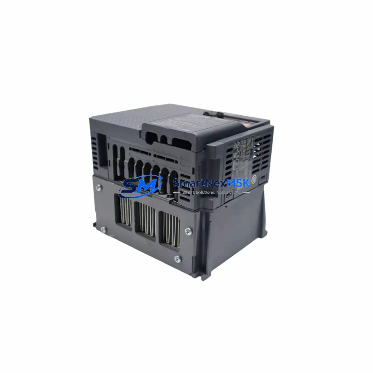
The Mitsubishi Electric GX41N is a 32-point DC input module engineered for the MELSEC-Q Series programmable logic controller platform. As legacy MELSEC-A and MELSEC-AnS systems reach end-of-life and spare parts become increasingly scarce, the GX41N has emerged as a primary retrofit solution for engineers tasked with modernizing aging production lines without full system replacement. Its wiring-compatible terminal layout, standard Q-series backplane interface, and GX Works2/GX Works3 compatibility make it one of the most practical upgrade paths available for facilities running Mitsubishi-based control architectures.
Whether you are replacing a failed QX41 or QX40 input module, migrating from an older A1SX41 or A1SX40 on a MELSEC-A rack, or consolidating I/O across a multi-drop CC-Link network, the GX41N delivers the signal density and electrical compatibility required for a controlled, low-risk cutover. Each unit shipped from our Xiamen warehouse undergoes functional verification against Mitsubishi’s published input specifications before dispatch.
Upgrade Compatibility Table
| Parameter | GX41N (This Unit) | Legacy Reference (QX41 / A1SX41) |
|---|---|---|
| Input Points | 32 points | 32 points |
| Input Voltage | DC 24V (12–24V range) | DC 24V |
| Backplane Interface | Q-series bus connector | Q-series / A-series (adapter required for A-series) |
| Terminal Block | 40-pin removable terminal | 40-pin (QX41) / 40-pin (A1SX41) |
| Wiring Compatibility | Direct drop-in for QX41 wiring harness | Verify pin mapping for A-series migration |
| Communication Protocol | Q-bus internal / CC-Link via master | A-bus / CC-Link (via QJ61BT11N master) |
| GX Works Compatibility | GX Works2, GX Works3 | GX Developer (legacy), GX Works2 |
| Installation Slot | Any Q-series main base or extension base | A-series main base (not interchangeable without adapter) |
| Retrofit Recommendation | Direct replacement for QX41; use QA1S65B adapter for A-series base | — |
| Commissioning Note | Verify I/O assignment in GX Works parameter table after slot insertion | Re-map addresses if migrating from A-series addressing scheme |
| Warranty | 12 Months | — |
Retrofit Planning for Existing Automation Systems
A successful GX41N retrofit begins well before the module arrives on site. Engineers should start by auditing the existing control cabinet to confirm available slots on the Q38B or Q312B main base, or on any Q65B extension base connected via the QC05B extension cable. If the installation is migrating from a MELSEC-A platform, the QA1S65B A/Q conversion adapter base must be sourced alongside the GX41N to bridge the mechanical and electrical differences between the two backplane generations.
Power budget verification is a critical pre-installation step. The Q61P or Q62P power supply module feeding the base must have sufficient 5VDC internal bus capacity to support the GX41N’s consumption alongside other installed modules such as the QJ71E71-100 Ethernet communication module or the QJ61BT11N CC-Link master module. Overloading the internal bus is a common cause of intermittent faults during commissioning and must be ruled out before powering up the retrofitted rack.
Terminal wiring should be documented and photographed before removal of the legacy module. The GX41N’s 40-pin removable terminal block accepts the same field wiring as the QX41, allowing the existing cable harness to transfer directly in most cases. For installations migrating from the A1SX41, engineers must cross-reference the terminal numbering against the GX41N wiring diagram, as the common terminal arrangement differs between the two generations. Label each wire before disconnection and verify continuity after reconnection using a loop tester before enabling the input scan.
Module address assignment in the Q-series parameter table must be updated in GX Works2 or GX Works3 to reflect the new slot position. If the GX41N is replacing a module in the same physical slot, the I/O address range will typically remain unchanged, simplifying program compatibility. However, if the slot position has shifted due to rack reconfiguration, all ladder logic referencing the affected X-device addresses must be reviewed and updated. The QD75MH4 positioning module and any QJ71C24N serial communication modules sharing the same rack should also be verified for address conflicts after the parameter update.
HMI screens connected via the GOT2000 series GT2710-VTBA or similar Mitsubishi HMI panels should be reviewed to confirm that any device tags mapped to the input module’s X-addresses remain valid after the retrofit. If the HMI project references symbolic device names rather than absolute addresses, the update scope is minimal. For projects using direct address references, a tag audit in GT Designer3 is recommended before returning the line to production.
Downtime Control During System Migration
Minimizing unplanned downtime during a GX41N retrofit requires a structured cutover plan. The recommended approach is to perform all preparatory work — parameter editing in GX Works, HMI tag verification, power budget calculation, and terminal labeling — during scheduled maintenance windows before the physical swap takes place. This reduces the live cutover to a module exchange and a controlled power cycle, typically achievable within 30 to 60 minutes for a single-slot replacement.
Before removing the legacy module, use GX Works to perform a full program backup to a local PC and to the Q4MEMS memory cassette if installed. This preserves the original program logic and parameter set as a recovery baseline. After inserting the GX41N and restoring power, perform a forced input test using the GX Works device monitor to verify that all 32 input channels respond correctly to field signals before releasing the line to automatic operation.
For installations where continuous process control is required, consider staging the retrofit during a planned production changeover rather than a reactive maintenance event. Pre-testing the GX41N on a bench rack using a Q00UJCPU or equivalent Q-series CPU with a simulated input signal source allows the module to be verified against the target program before it enters the production environment, further reducing the risk of extended downtime.
All units supplied by SMARTNEXMSK are tested prior to shipment and include a 12-month warranty covering manufacturing defects and functional failures under normal operating conditions. Replacement or repair is arranged promptly to minimize impact on production continuity.
Retrofit Support FAQ
Q1: Is the GX41N a direct drop-in replacement for the QX41?
Yes. The GX41N shares the same 32-point DC input specification, Q-series backplane connector, and 40-pin terminal block layout as the QX41. In most installations, the existing field wiring transfers directly without modification. Verify the I/O address assignment in the GX Works parameter table after installation to confirm the slot mapping is correct.
Q2: Can the GX41N be used to replace an A1SX41 on a MELSEC-A rack?
The GX41N is a Q-series module and is not mechanically compatible with A-series main bases without an adapter. The QA1S65B A/Q conversion adapter base is required to mount Q-series modules on an A-series installation. Terminal wiring must also be cross-referenced, as the common terminal arrangement differs between the A1SX41 and GX41N. Address remapping in the program will be necessary if migrating from A-series X-device addressing.
Q3: What commissioning steps are required after installing the GX41N?
After physical installation, update the I/O parameter table in GX Works2 or GX Works3 to reflect the module’s slot position. Perform a forced input test via the device monitor to verify all 32 channels. Check the power supply module’s 5VDC internal bus load to confirm it is within rated capacity. If an HMI is connected, verify that all device tags mapped to the module’s X-addresses are resolving correctly in the GT Designer3 project before returning to automatic operation.
Q4: What does the 12-month warranty cover, and how is it claimed?
The 12-month warranty covers manufacturing defects and functional failures under normal operating conditions from the date of shipment. It does not cover damage resulting from incorrect installation, overvoltage, or physical mishandling. To initiate a warranty claim, contact SMARTNEXMSK with the order reference number and a description of the fault. Replacement units are dispatched promptly upon fault confirmation to minimize production impact.
© 2026 SMARTNEXMSK. All rights reserved.
Original Source: https://smartnexmsk.com
Contact: sales@smartnexmsk.com | +86 18259474341


