Mitsubishi S-K50/S-K65 Maintenance-Ready Spare S-K Series Automation
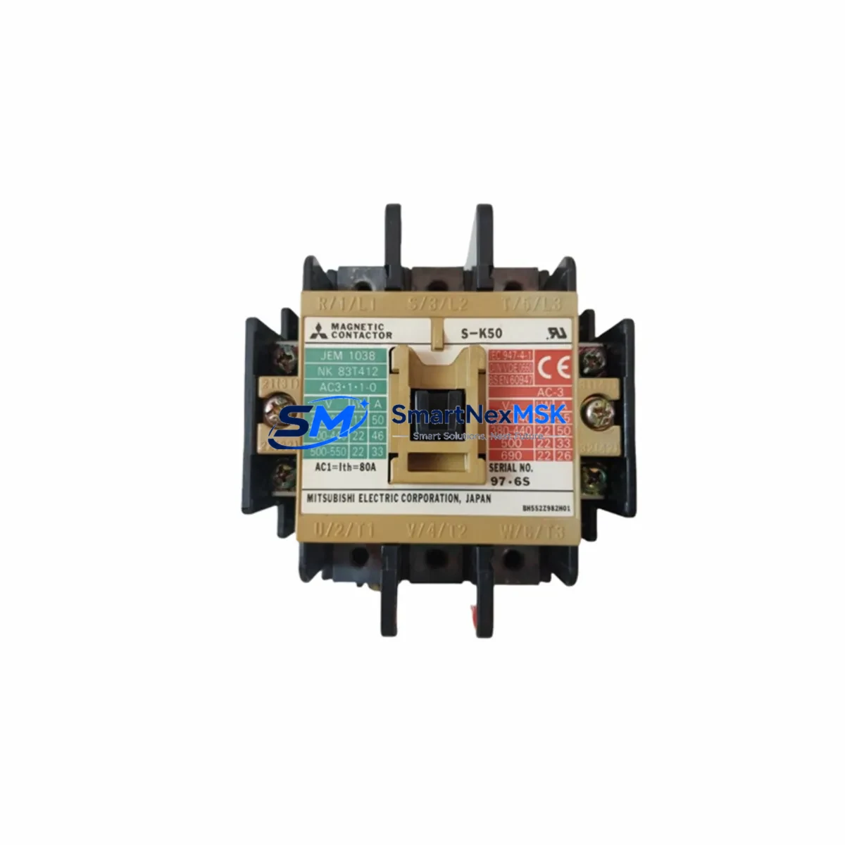
The Mitsubishi Electric S-K50 and S-K65 are high-performance AC magnetic contactors engineered for demanding industrial automation environments. As original spare parts within the S-K Series lineup, these contactors are designed to deliver reliable motor switching, load control, and circuit protection across a wide range of industrial applications — from conveyor drive panels and pump control stations to compressor starters and HVAC motor control centers. For maintenance engineers managing aging control systems or planning scheduled overhauls, stocking the S-K50/S-K65 as a ready-to-deploy spare is a proven strategy for minimizing unplanned downtime and accelerating fault recovery.
Whether you are responding to a contactor failure during a production shift or executing a planned replacement during a scheduled maintenance window, the S-K50/S-K65 offers direct compatibility with existing S-K Series panel layouts, terminal configurations, and DIN rail mounting standards. Its IEC 60947-4-1 compliance ensures it meets international safety and performance benchmarks, making it suitable for both domestic and export-oriented industrial installations.
Spare Maintenance Table
| Parameter | S-K50 | S-K65 |
|---|---|---|
| Type | AC Magnetic Contactor | |
| Series | S-K Series (Mitsubishi Electric) | |
| Rated Current (AC-3) | 50 A | 65 A |
| Rated Voltage | Up to 690 V AC | |
| Coil Voltage Options | 100–240 V AC / 24 V DC (model-dependent) | |
| Standard Compliance | IEC 60947-4-1, JIS C 8201-4-1 | |
| Mounting | DIN Rail / Panel Mount | |
| Auxiliary Contacts | 1NO + 1NC (standard configuration) | |
| Operating Temperature | -10°C to +60°C | |
| Enclosure Rating | IP20 (open type) | |
| Origin | Japan | |
| Application | Motor control, load switching, conveyor, pump, compressor, HVAC | |
| Compatibility | S-K Series panels; replaces S-K50 / S-K65 directly | |
| Warranty | 12 Months from shipment date | |
| Shipment Inspection | Tested and verified before dispatch | |
Maintenance Planning for Continuous Operation
When replacing the S-K50 or S-K65 in a live control panel, a thorough maintenance inspection of the surrounding circuit is essential to prevent repeat failures and ensure long-term system stability. Maintenance engineers should begin by verifying the coil supply voltage using the panel’s 24 V DC or 100–240 V AC control power rail — a degraded or fluctuating control power supply is a common root cause of premature contactor failure. The thermal overload relay paired with the contactor, typically a TH-K Series overload relay from Mitsubishi Electric, should be inspected for trip history, calibration drift, and contact wear before reinstallation.
The main power terminals and incoming cable lugs should be checked for signs of overheating, oxidation, or loose torque — particularly on the L1/L2/L3 input and T1/T2/T3 output terminals. If the contactor is part of a star-delta starter circuit, the associated S-K Series timer relay and the secondary contactor in the delta leg should also be evaluated for contact erosion and coil response time. For panels incorporating Mitsubishi MCCB (Molded Case Circuit Breakers) such as the NF or NV Series upstream of the contactor, breaker trip curves and contact resistance should be verified to confirm coordination with the new contactor’s rated current.
In PLC-controlled systems where the S-K50/S-K65 is driven by a Mitsubishi MELSEC Q Series or iQ-R Series output module, the digital output card’s channel current capacity and response time should be confirmed against the contactor coil inrush specification. Auxiliary contact feedback wiring to the PLC input module — used for run/stop confirmation and fault interlocking — should be continuity-tested after installation. Where signal isolation is required between the PLC output and the contactor coil circuit, a signal isolator or interposing relay module should be inspected for contact bounce and isolation integrity.
Terminal blocks on the contactor’s auxiliary circuit, including those connected to indicator lamps, HMI digital inputs, or SCADA I/O cards, should be re-torqued and inspected for insulation degradation. If the panel includes a GOT Series HMI (Graphic Operation Terminal) monitoring motor run status, the associated bit device address mapped to the contactor feedback should be verified in the ladder program after replacement. For older systems approaching end-of-life, this replacement event is also an appropriate time to audit the panel’s fuse holders, surge suppressors across the coil terminals, and any DIN rail-mounted power supply modules feeding the control circuit.
Site Replacement Workflow
Step 1 — Isolation and Lockout: De-energize the panel at the upstream MCCB or isolator. Apply LOTO (Lockout/Tagout) procedure. Confirm zero voltage at the contactor main terminals using a calibrated multimeter.
Step 2 — Documentation: Photograph the existing wiring layout, terminal numbering, and auxiliary contact connections before removal. Record the coil voltage marking and any add-on auxiliary contact blocks (e.g., CA-K Series) fitted to the original unit.
Step 3 — Removal: Disconnect main power cables (L1/L2/L3, T1/T2/T3) and control wiring from auxiliary terminals. Release the DIN rail locking tab and remove the contactor from the rail.
Step 4 — Verification: Confirm the replacement S-K50 or S-K65 matches the original coil voltage, frame size, and auxiliary contact configuration. Check that any add-on contact blocks are compatible and re-attach as required.
Step 5 — Installation and Torque: Mount the new contactor on the DIN rail. Reconnect all terminals per the original wiring documentation. Apply manufacturer-specified torque values to all power and control terminals.
Step 6 — Functional Test: Re-energize the control circuit only. Manually energize the coil via the PLC output or test button. Confirm main contact closure, auxiliary feedback signal to PLC input, and HMI status indication. Then restore main power and perform a loaded test run.
This workflow is applicable whether replacing a failed unit during an emergency shutdown or executing a proactive swap during a planned maintenance outage. The S-K50/S-K65’s direct form-fit-function compatibility with the S-K Series panel layout eliminates the need for wiring modifications, reducing total replacement time to under 30 minutes for experienced maintenance personnel.
Spare Parts Support FAQ
Q1: Is the S-K50/S-K65 supplied as a genuine Mitsubishi Electric original spare?
Yes. All units are sourced as original Mitsubishi Electric components. Each unit is inspected and tested prior to shipment to confirm coil operation, contact resistance, and mechanical integrity. A 12-month warranty is provided from the date of shipment.
Q2: What is the recommended spare parts stocking strategy for S-K Series contactors?
For facilities operating multiple S-K Series motor control panels, a minimum stock of one S-K50 and one S-K65 per panel section is recommended. Given the typical 5–10 year service life of contactors in continuous-duty applications, proactive replacement at the 7-year mark — or upon detection of contact wear, coil noise, or slow pull-in — is advisable to prevent unplanned outages.
Q3: Can the S-K65 directly replace an S-K50 in an existing panel?
The S-K65 shares the same S-K Series frame and DIN rail footprint as the S-K50, but its higher rated current (65 A vs. 50 A) means it is suitable as an uprated replacement where load growth has occurred. Coil voltage and auxiliary contact configuration must be verified to match the existing circuit before substitution. Consult the panel’s electrical schematic and the Mitsubishi Electric S-K Series catalog for confirmation.
Q4: What pre-shipment testing is performed on each unit?
Each S-K50/S-K65 unit undergoes coil energization testing, main contact continuity verification, and mechanical operation inspection before dispatch. Units are packaged in anti-static protective packaging with original manufacturer labeling. Shipment documentation includes part number, quantity, and inspection confirmation.
—
© 2026 SMARTNEXMSK. All rights reserved.
Original Source: https://smartnexmsk.com
Contact: sales@smartnexmsk.com | +86 18259474341


