Mitsubishi S-N65 Retrofit-Ready Contactor for S-N Series Control Systems
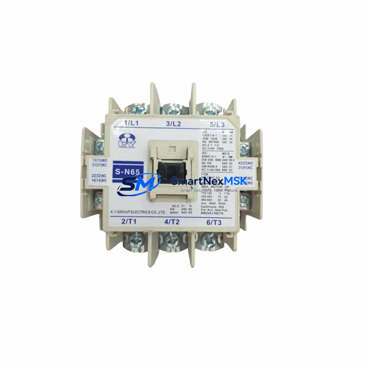
The Mitsubishi Electric S-N65 is a 65A AC magnetic contactor engineered for seamless integration into existing S-N Series motor control and power distribution panels. As legacy contactors reach end-of-life or become difficult to source, the S-N65 serves as a verified drop-in replacement that preserves original wiring layouts, DIN rail mounting positions, and coil voltage configurations — minimising retrofit risk and eliminating the need for panel redesign. Whether you are restoring a tripped motor starter circuit, upgrading an ageing control cabinet, or expanding I/O capacity on a production line, the S-N65 delivers the electrical performance and dimensional compatibility required for a controlled, low-downtime changeover.
Industrial facilities operating Mitsubishi MELSEC Q-series or iQ-R series PLCs frequently pair the S-N65 with upstream protection devices such as the NF63-CV or NF125-CV moulded-case circuit breakers to form a coordinated motor protection group. In retrofit scenarios where the original contactor was mounted alongside a TH-N Series thermal overload relay, the S-N65 maintains the same auxiliary contact block interface, allowing the existing TH-N60 or TH-N120 relay to be reused without rewiring. This is particularly valuable in multi-motor drive panels where simultaneous replacement of all protection components would extend planned maintenance windows beyond acceptable limits.
For control system integrators migrating from older MELSEC A-series or FX-series architectures to current iQ-F or iQ-R platforms, the S-N65 fits within the same cabinet footprint as predecessor models, preserving the physical layout of the power distribution section while the PLC backplane, RJ71GF11-T2 CC-Link IE Field Network master module, and associated RX40C7 or RY40P5B remote I/O modules are upgraded in a separate phase. This phased approach — updating the control layer first and the power switching layer independently — is a proven strategy for reducing total migration risk on continuous-process lines where a full simultaneous cutover is not operationally feasible.
When planning a retrofit using the S-N65, engineers should verify the following parameters against the existing installation: coil operating voltage (100–240V AC or 24V DC options), rated operational current at the applicable utilisation category (AC-3 for squirrel-cage motors, AC-4 for reversing or plugging duty), auxiliary contact configuration (standard 1NO+1NC or supplementary contact blocks), and terminal torque specifications to ensure compatibility with existing cable lugs and busbar connections. Where the original contactor was wired with a CA-N Series surge suppressor across the coil terminals, the same suppressor can be retained on the S-N65 coil circuit without modification.
In distributed control architectures where the S-N65 is commanded via a QY40P transistor output module or an RY10R2 relay output module on a MELSEC rack, the coil inrush and sealed current characteristics of the S-N65 fall within the rated output current of standard Mitsubishi digital output modules, eliminating the need for interposing relays in most applications. For installations using GOT2000 Series HMI panels with motor status monitoring screens, the auxiliary contact outputs of the S-N65 can be mapped directly to existing screen tag addresses, preserving HMI logic without reprogramming.
Pre-shipment testing on every S-N65 unit includes coil pull-in and drop-out voltage verification, contact resistance measurement, and insulation resistance testing to IEC 60947-4-1 standards. Units are supplied with a test certificate and are covered by a 12-month warranty from the date of dispatch. Stock is maintained for immediate dispatch, supporting urgent breakdown replacement requirements where extended lead times on OEM channels are not acceptable.
Upgrade Compatibility Table
| Parameter | Detail |
|---|---|
| SKU / Model | S-N65 |
| Brand | Mitsubishi Electric |
| Series | S-N Series Magnetic Contactors |
| Rated Current (AC-3) | 65A |
| Coil Voltage Options | 100–240V AC / 24V DC (specify on order) |
| Mounting | DIN rail (EN 60715) or screw-mount panel |
| Auxiliary Contacts | 1NO + 1NC standard; supplementary blocks available |
| Utilisation Category | AC-3, AC-4 (IEC 60947-4-1) |
| Common Replaced Models | S-N50, S-N80 (with derating review) |
| Compatible Overload Relay | TH-N60, TH-N120 (direct mount) |
| Compatible MCCB | NF63-CV, NF125-CV (upstream protection) |
| PLC Output Compatibility | QY40P, RY10R2, RY40P5B (no interposing relay required) |
| Communication Protocol | N/A (hardwired; status via auxiliary contacts to PLC DI) |
| Commissioning Note | Verify coil voltage, terminal torque, and auxiliary contact mapping before energising |
| Warranty | 12 months from dispatch date |
| Origin | Japan |
Retrofit Planning for Existing Automation Systems
A successful S-N65 retrofit begins with a thorough audit of the existing motor control centre (MCC) or control cabinet. Identify the current contactor model, coil voltage, and auxiliary contact wiring before ordering. In panels where the S-N65 replaces an older S-N50 unit on a lightly loaded circuit, no derating calculation is required; however, if the replacement is for an S-N80 on a heavily loaded feeder, a current audit should confirm that the 65A rating is adequate for the actual motor FLA plus service factor. The physical envelope of the S-N65 is compatible with standard S-N Series mounting rails, so no busbar modification or panel cutout enlargement is typically required.
In multi-axis servo and variable-frequency drive (VFD) panels, the S-N65 is commonly used as the main incoming contactor ahead of a FR-A800 Series inverter, providing a controlled power isolation point for maintenance without requiring the drive to be de-energised from the upstream MCCB. The auxiliary contact output is wired to a QX40 or RX40C7 digital input module on the MELSEC rack to provide run/fault status feedback to the PLC program. Where a GOT2000 GT27 HMI is installed, the contactor status tag is typically already defined in the GT Designer3 project; replacing the physical contactor does not require any HMI screen modification provided the auxiliary contact wiring is preserved.
For installations involving CC-Link IE Field Network or MELSECNET/H distributed I/O, the S-N65 coil command and status feedback are handled through remote I/O stations. Confirm the remote station address assignments in GX Works3 before the cutover to ensure that the new contactor responds to the correct output coil address in the PLC program. If the original program used a latching coil instruction (SET/RST) rather than a standard OUT instruction, verify that the auxiliary contact interlock logic is intact after rewiring.
Downtime Control During System Migration
Minimising unplanned downtime during a contactor replacement requires preparation before the maintenance window opens. Key steps include: backing up the current PLC program from the Q03UDECPU or R04CPU to a laptop running GX Works3 before any power is removed; photographing the existing terminal wiring and labelling all conductors with ferrule markers; and confirming that the replacement S-N65 coil voltage matches the control circuit supply before installation.
Where the control system includes a QJ71E71-100 Ethernet module or RJ71EN71 for remote monitoring, the PLC can remain in RUN mode during the physical contactor swap if the motor circuit is isolated at the upstream MCCB and the PLC output for the contactor coil is forced OFF in GX Works3 online mode. This approach preserves the communication link to the SCADA or DCS host, avoids a full system restart, and allows the maintenance team to verify contactor operation by forcing the output ON from the engineering workstation before returning control to the automatic sequence. Total planned downtime for a single S-N65 replacement using this method is typically 15–30 minutes for a prepared team.
After installation, perform a no-load test by energising the coil and confirming pull-in voltage, then verify auxiliary contact continuity with a multimeter before reconnecting the motor load. Log the replacement in the plant maintenance system with the new unit serial number and the 12-month warranty expiry date.
Retrofit Support FAQ
Q1: Is the S-N65 a direct drop-in replacement for the S-N50?
Yes, in most applications. The S-N65 shares the same DIN rail footprint and terminal layout as the S-N50. The higher current rating provides additional headroom for motor starting duty. Confirm coil voltage and auxiliary contact configuration match your existing wiring before installation.
Q2: What commissioning checks are required after installation?
Verify coil pull-in and drop-out voltage against the control circuit supply, confirm auxiliary contact operation with a continuity test, check all terminal torque values against the S-N65 installation manual, and perform a no-load energisation test before reconnecting the motor. If the contactor is commanded by a PLC output module, force the output ON in GX Works3 to confirm correct operation before returning to automatic mode.
Q3: Can the existing TH-N Series thermal overload relay be reused?
Yes. The S-N65 accepts direct-mount TH-N60 and TH-N120 thermal overload relays using the standard S-N Series mounting interface. No adapter bracket is required. Reset the overload relay trip current setting to match the motor nameplate FLA after installation.
Q4: What does the 12-month warranty cover?
All S-N65 units are covered by a 12-month warranty from the dispatch date against manufacturing defects and premature failure under normal operating conditions. Each unit is pre-tested for coil voltage, contact resistance, and insulation resistance before dispatch. Warranty claims are supported with a replacement unit dispatched upon receipt of the failed unit and confirmation of the fault.
© 2026 SMARTNEXMSK. All rights reserved.
Original Source: https://smartnexmsk.com
Contact: sales@smartnexmsk.com | +86 18259474341


