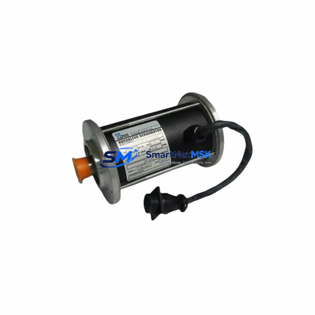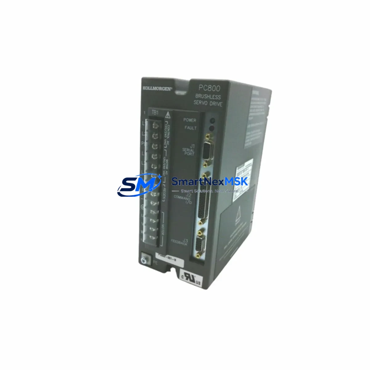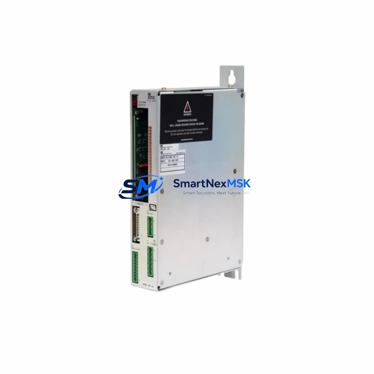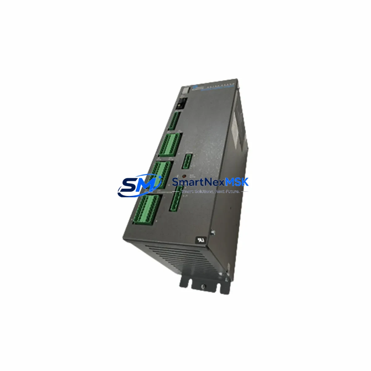
Pacific Scientific SC752A-001-01 Maintenance-Ready Spare for SC700 Automation
The Pacific Scientific SC752A-001-01 is a brushless AC servo amplifier designed for the SC700 series motion control platform. As a critical drive component in precision automation systems, this unit governs torque, velocity, and position loops for servo axes in manufacturing, packaging, printing, and process control environments. When an SC752A-001-01 fails or degrades, the result is immediate axis loss and unplanned downtime — making a verified, tested spare essential for any maintenance-ready operation.
SMARTNEXMSK supplies the SC752A-001-01 as an original industrial spare, fully tested prior to shipment, with a 12-month warranty. Each unit is inspected for power stage integrity, feedback interface continuity, and communication bus response before dispatch. Our inventory is maintained for long-term supply continuity, supporting both emergency replacement and planned maintenance cycles.
Spare Maintenance Table
| Parameter | Specification / Notes |
|---|---|
| Part Number | SC752A-001-01 |
| Brand | Pacific Scientific |
| Series | SC700 |
| Product Type | Brushless AC Servo Amplifier |
| Compatibility | SC700 series servo systems; SC750, SC752, SC755 platform |
| Input Voltage | AC 115/230V single or three-phase (model-dependent) |
| Output | Variable frequency PWM drive for brushless servo motors |
| Feedback Interface | Encoder (incremental/absolute), resolver compatible |
| Communication | RS-232/RS-485 serial; optional fieldbus (DeviceNet/Profibus) |
| Mounting | Panel mount, DIN rail adaptable |
| Operating Temperature | 0°C to 45°C ambient |
| Application Environment | Industrial control cabinets, motion control panels |
| Maintenance Recommendation | Inspect cooling fan, DC bus capacitors, and feedback wiring annually |
| Origin | USA |
| Warranty | 12 Months — tested and verified before shipment |
Maintenance Planning for Continuous Operation
Replacing an SC752A-001-01 in the field is rarely an isolated task. Maintenance engineers and procurement teams should treat this amplifier replacement as an opportunity to audit the surrounding electrical circuit and control cabinet for latent faults that may have contributed to the original failure or that could cause a repeat event.
Begin with the servo power supply: verify that the DC bus voltage is within specification and that the regenerative braking resistor (if fitted) shows no signs of thermal stress. A degraded power supply feeding the SC700 drive bus is a common root cause of premature amplifier failure. Inspect the input line filter and any associated EMI suppression components for continuity and insulation integrity.
Check all motor feedback cables — encoder or resolver — for shield continuity, connector seating, and insulation damage. A marginal feedback signal can cause the SC752A-001-01 to fault on position error or overspeed even after the amplifier itself is replaced. If the system uses a SC700-compatible resolver-to-digital converter board, verify its output signal quality before commissioning the new unit.
Inspect the I/O interface wiring at the amplifier’s control connector: enable signals, fault reset lines, analog command inputs (±10V), and digital I/O for limit switches and home sensors. Corroded terminals or intermittent connections at the terminal block assemblies in the control cabinet are a frequent source of nuisance faults that are misdiagnosed as amplifier failures.
If the SC700 axis is coordinated by a motion controller or PLC — such as a Kollmorgen AKD master, a Rockwell ControlLogix with servo module, or a Siemens S7 with FM357 — verify that the controller’s axis parameters (current limits, velocity feedforward, position window) are correctly restored after the amplifier swap. Parameter loss during a drive replacement is a common cause of post-maintenance instability.
For systems using DeviceNet or Profibus communication modules integrated with the SC700 platform, confirm node addressing and baud rate settings match the network configuration before enabling the axis. A communication timeout on the fieldbus can prevent the amplifier from accepting the run command even when the hardware is fully functional.
Also inspect the 24VDC control power supply that feeds the amplifier’s logic board and I/O circuits. An undersized or aging SMPS unit can cause intermittent logic faults that mimic amplifier hardware failure. Similarly, check any safety relay modules or STO (Safe Torque Off) wiring in the drive enable circuit — a degraded safety relay contact is a common cause of enable signal instability.
Finally, review the HMI or operator panel for any stored fault history that may indicate whether the failure was sudden (power event, short circuit) or gradual (thermal, feedback degradation). This history guides the scope of the surrounding inspection and helps justify spare parts procurement decisions to plant management.
Site Replacement Workflow
Step 1 — Isolation: De-energize the control cabinet and lock out / tag out (LOTO) the main disconnect. Discharge the DC bus capacitors per the SC700 service manual (minimum 5-minute wait after power-off).
Step 2 — Documentation: Photograph all wiring connections, DIP switch settings, and parameter configuration screens on the HMI or PC commissioning tool before disconnecting the failed unit. The SC752A-001-01 stores axis parameters in non-volatile memory; if the replacement unit ships with factory defaults, all parameters must be re-entered.
Step 3 — Removal: Disconnect the motor power cable (U/V/W), feedback cable, control connector, and DC bus connections in sequence. Remove the amplifier from its mounting rail or panel.
Step 4 — Installation: Mount the replacement SC752A-001-01, reconnect all cables in reverse order, and verify torque on all terminal screws. Confirm DIP switch settings match the documented configuration.
Step 5 — Parameter Restore: Upload the saved parameter file via RS-232/RS-485 or re-enter parameters manually. Verify motor nameplate data, encoder resolution, current limits, and velocity loop gains.
Step 6 — Commissioning: Apply control power first (24VDC logic), verify no fault LEDs, then apply main AC power. Perform a low-speed jog test before returning the axis to automatic mode. Confirm position accuracy and fault-free operation over at least one full production cycle before signing off.
This workflow minimizes downtime, ensures system compatibility, and reduces the risk of repeat failure — keeping your SC700 motion system operational and your maintenance records complete.
Spare Parts Support FAQ
Q1: Is the SC752A-001-01 a direct drop-in replacement for other SC700 series amplifiers?
The SC752A-001-01 is a specific variant within the SC700 platform. While it shares the same mechanical form factor and communication interface as other SC75x models, current rating and feedback configuration may differ. Always verify the motor nameplate current and feedback type against the amplifier’s rated output before installation. SMARTNEXMSK can assist with compatibility confirmation prior to shipment.
Q2: How is the unit tested before shipment?
Each SC752A-001-01 supplied by SMARTNEXMSK undergoes a functional power-on test, DC bus voltage verification, feedback interface continuity check, and communication port response test. Units that do not pass all test points are not shipped. A test record is available upon request.
Q3: What does the 12-month warranty cover?
The warranty covers hardware defects and functional failure under normal operating conditions for 12 months from the date of shipment. It does not cover damage caused by incorrect installation, overvoltage events, or unauthorized modification. In the event of a warranty claim, SMARTNEXMSK will arrange replacement or repair at no additional cost.
Q4: Can you support long-term or blanket spare parts orders for the SC752A-001-01?
Yes. SMARTNEXMSK maintains ongoing inventory of SC700 series components to support planned maintenance programs, annual shutdown kits, and multi-site spare parts standardization. Contact our team to discuss volume pricing, lead time commitments, and consignment stock arrangements.
© 2026 SMARTNEXMSK. All rights reserved.
Original Source: https://smartnexmsk.com
Contact: [email protected] | +86 18259474341