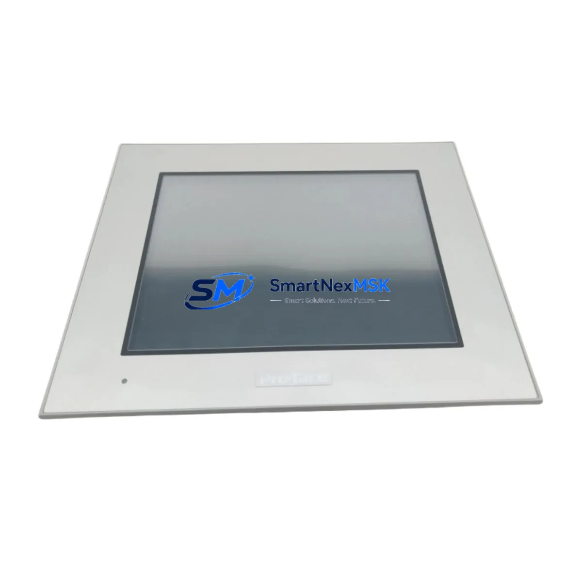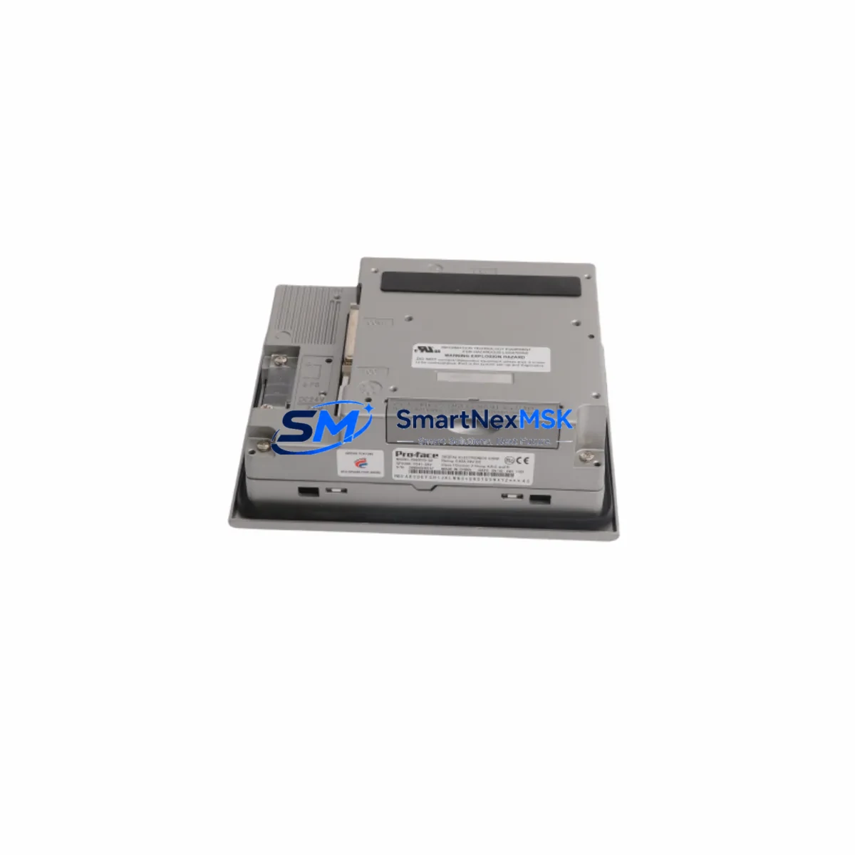
Proface 5302-MBP-MCM4 Retrofit-Ready Modbus Plus Gateway for Quantum Control Systems
The Proface 5302-MBP-MCM4 is a Modbus Plus communication gateway module engineered for seamless integration into Schneider Electric Quantum-series PLC backplanes. As legacy Modicon Quantum installations age and original Modbus Plus interface cards become increasingly difficult to source, the 5302-MBP-MCM4 provides a verified, drop-in compatible replacement path that preserves existing network topology, ladder logic, and HMI communication links without requiring a full control system redesign.
Industrial facilities running Schneider Quantum 140 CPU series controllers — including the 140CPU43412, 140CPU65150, and 140CPU67160 — frequently rely on Modbus Plus as the primary peer-to-peer network connecting PLCs, remote I/O drops, and operator stations. When the original Modbus Plus communication card fails or reaches end-of-life, unplanned downtime can cascade across the entire production line. The 5302-MBP-MCM4 is stocked and tested to restore network continuity with minimal engineering intervention.
Each unit shipped from SMARTNEXMSK undergoes functional verification including power-on self-test, Modbus Plus token-passing confirmation, and backplane slot communication checks before dispatch. A 12-month warranty covers all hardware defects from the date of invoice.
Upgrade Compatibility Table
| Parameter | Details |
|---|---|
| Replacement Target | Proface 5302-MBP-MCM4 (OEM equivalent) |
| Compatible Series | Schneider Electric Quantum 140-series backplanes |
| Communication Protocol | Modbus Plus (MB+), peer-to-peer token ring |
| Backplane Interface | Quantum I/O bus, standard single-slot form factor |
| Network Ports | Dual MB+ ports (daisy-chain or redundant ring topology) |
| Installation Requirement | Quantum-compatible rack; no additional adapter required |
| Address Configuration | Rotary switch (node address 1–64) |
| Power Draw | Supplied via backplane; verify 140CPS11100 or 140CPS21100 PSU capacity |
| Program Compatibility | Existing Concept, ProWORX, or Unity Pro MB+ routing tables retained |
| HMI Compatibility | Compatible with Magelis XBTGT/XBTGK series and third-party MB+ HMI nodes |
| Commissioning Tool | Modbus Plus Network Analyzer (MBPSTAT) or Concept v2.6+ |
| Warranty | 12 months from invoice date |
Retrofit Planning for Existing Automation Systems
A successful retrofit of the 5302-MBP-MCM4 into an operating Quantum system begins well before the module arrives on site. Engineers should first audit the existing Quantum rack configuration — noting the slot position of the current Modbus Plus card, the rack type (140XBP01600, 140XBP01000, or 140XBP00600), and the total power budget consumed by installed modules including 140ACI03000 analog input cards, 140DDI35300 discrete input modules, and 140DAO84000 analog output modules. Confirming that the 140CPS11100 or 140CPS21100 power supply has sufficient headroom for the replacement module prevents post-installation faults.
Terminal wiring on the Modbus Plus trunk cable — typically a Belden 9841 shielded twisted pair — must be inspected for correct polarity, shield grounding at a single point, and proper 100-ohm termination resistors at both ends of the network segment. Node address conflicts are a common commissioning error: the rotary address switch on the 5302-MBP-MCM4 must be set to a unique value not already occupied by other devices on the MB+ ring, including remote I/O head-end adapters such as the 140CRA93100 or 140CRA31908.
Before powering down the rack for module swap, export the current Concept or Unity Pro project file and document all MB+ routing table entries, peer-copy (MSTR) function block configurations, and global data table addresses. This ensures that after the 5302-MBP-MCM4 is seated and the rack is powered on, the CPU can immediately re-establish peer communication without requiring logic modifications. If the facility uses a Magelis XBTGT5330 or similar HMI panel connected via Modbus Plus, verify that the HMI node address and communication driver settings remain unchanged — the new module is transparent to the HMI layer once the network token is re-established.
For systems that also incorporate a 140NOE77100 Ethernet TCP/IP module or a 140NOM21100 Modbus Plus network option module for bridging to Modicon Momentum or Premium PLCs, confirm that the MB+ network map in the CPU’s configuration still reflects the correct node count after the swap. Unity Pro’s MB+ network browser tool provides a live view of all active nodes and is the fastest way to confirm successful integration.
Downtime Control During System Migration
Minimizing production downtime during a Modbus Plus gateway replacement requires a structured hot-swap preparation protocol. Where the process allows a controlled shutdown window, coordinate with operations to schedule the swap during a planned maintenance interval — ideally when the 140CPU is already in stop mode for a scheduled program update or safety inspection.
Before removing the original module, use MBPSTAT or the Concept network diagnostics tool to capture a baseline of all active MB+ nodes, their addresses, and current token-passing statistics. This snapshot serves as the acceptance criterion after the 5302-MBP-MCM4 is installed: all previously active nodes must reappear within two to three token-rotation cycles of power-up.
The original ladder logic and derived function blocks stored in the 140CPU’s battery-backed RAM are not affected by the communication module swap — program integrity is preserved as long as the CPU battery (typically a 3.6V lithium cell) is healthy and the rack power is restored within the CPU’s memory-hold specification. For systems using a 140EHC10500 high-speed counter module or 140MSB10100 Modbus serial port module in the same rack, these modules continue to operate independently during the MB+ card replacement and do not require re-initialization.
Once the 5302-MBP-MCM4 is seated and the rack is energized, allow 30–60 seconds for the module’s self-test and token acquisition sequence to complete before placing the CPU back into run mode. Monitor the module’s MB+ status LEDs: a steady green TOKEN LED confirms active participation in the network ring. If the LED remains amber or flashes red, recheck node address uniqueness and cable termination before escalating to a full network trace.
Retrofit Support FAQ
Q1: Is the 5302-MBP-MCM4 a direct drop-in replacement for the original Proface Modbus Plus card in a Quantum rack?
Yes. The 5302-MBP-MCM4 uses the standard Quantum single-slot backplane connector and requires no adapter bracket or firmware update on the CPU side. Set the rotary node address switch to match the original card’s address before installation.
Q2: Will my existing Concept or Unity Pro program need to be modified after the swap?
No program modifications are required provided the node address is set identically to the replaced card. All MSTR function blocks, peer-copy configurations, and MB+ routing table entries remain valid. A full online download is not necessary — the CPU will resume communication automatically once the new module acquires the network token.
Q3: How do I verify correct wiring and termination before powering up?
Use a digital multimeter to confirm 100-ohm resistance across the MB+ trunk cable at each network end with all devices powered off. Verify shield continuity and single-point grounding. Check that the Belden 9841 cable polarity (+ and −) is consistent at every connector. Incorrect termination is the most common cause of token-passing failures on Modbus Plus networks.
Q4: What does the 12-month warranty cover, and what is the return process?
The 12-month warranty covers all hardware defects in materials and workmanship from the invoice date. Each unit is functionally tested prior to shipment. If a defect is identified within the warranty period, contact sales@smartnexmsk.com with the invoice number and a description of the fault. SMARTNEXMSK will arrange a replacement or repair at no additional cost. Physical damage caused by incorrect installation, overvoltage, or improper handling is excluded from warranty coverage.
© 2026 SMARTNEXMSK. All rights reserved.
Original Source: https://smartnexmsk.com
Contact: sales@smartnexmsk.com | +86 18259474341