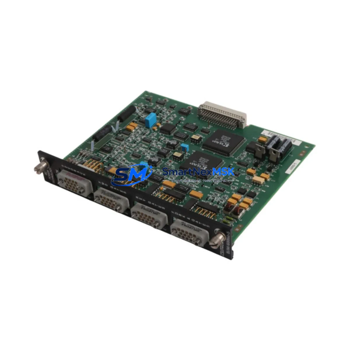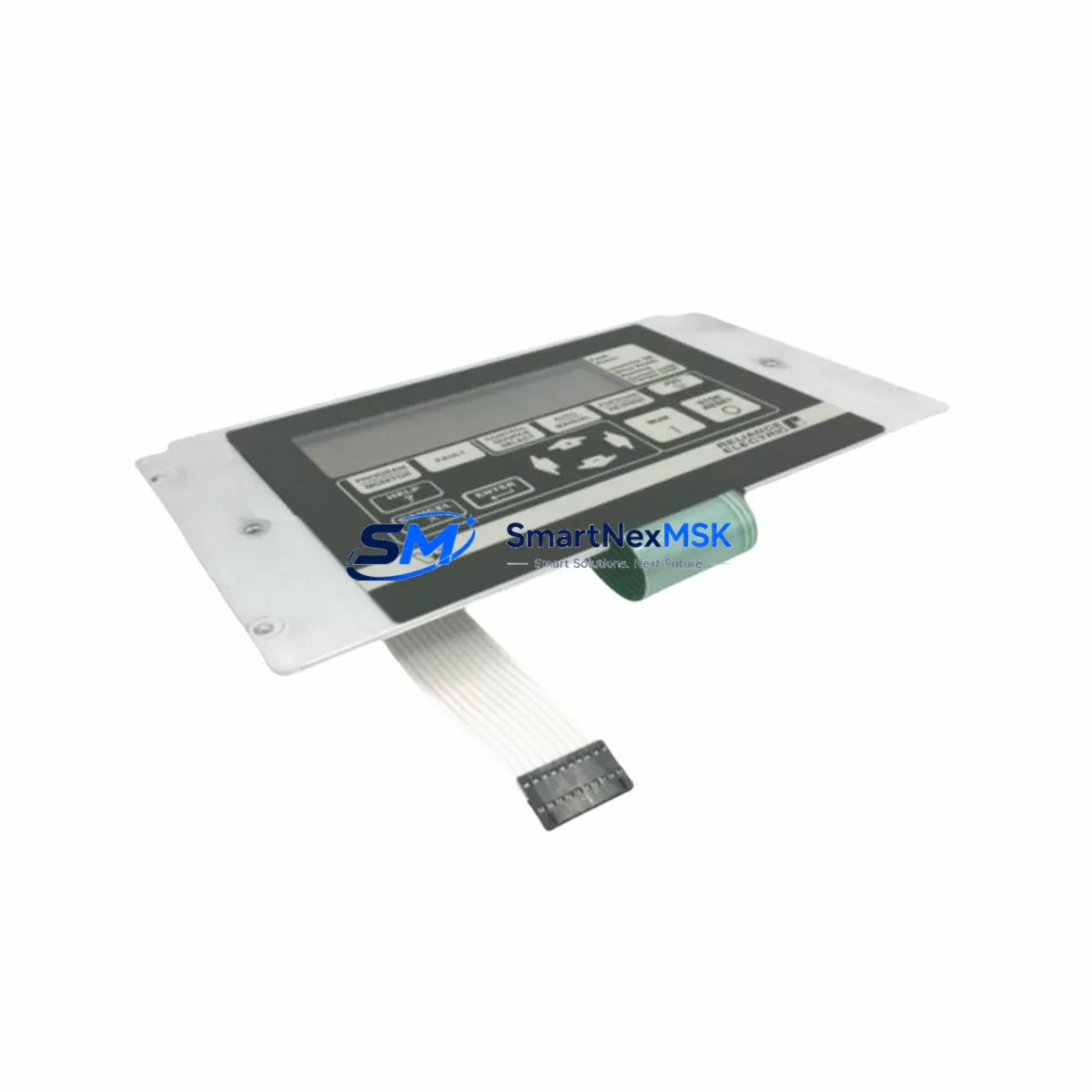
RELIANCE 802273-14R Retrofit-Ready Interface Module for AutoMax Control Systems
The RELIANCE 802273-14R is a retrofit-ready interface module engineered for seamless integration into legacy AutoMax distributed control architectures. As industrial facilities face increasing pressure to modernize aging control infrastructure without full system overhauls, the 802273-14R provides a validated, drop-in upgrade path that preserves existing wiring, backplane connections, and program logic — minimizing engineering risk and unplanned downtime during migration.
Whether you are replacing a failed unit on an active production line, upgrading a control cabinet as part of a phased modernization program, or sourcing discontinued spare parts to extend the operational life of an AutoMax-based system, the 802273-14R is stocked, tested, and ready for immediate dispatch with a 12-month warranty.
Upgrade Compatibility Table
| Parameter | Details |
|---|---|
| Compatible Series | RELIANCE AutoMax Distributed Control System |
| Module Type | Interface Module |
| Backplane Interface | AutoMax rack-compatible backplane slot |
| Communication Protocol | AutoMax proprietary network; compatible with existing AutoMax communication links |
| Terminal Wiring | Retains original terminal block layout — no rewiring required for direct replacement |
| Installation Requirement | Standard DIN-rail or rack-mount; confirm slot address assignment before insertion |
| Replacement Recommendation | Direct replacement for original 802273-14R; verify firmware revision compatibility |
| Commissioning Notes | Confirm module address, I/O mapping, and HMI tag references before power-up |
| Warranty | 12 Months — covers manufacturing defects and functional failure under normal operating conditions |
| Outgoing Test | Each unit is functionally tested prior to shipment |
Retrofit Planning for Existing Automation Systems
Successful retrofit of the 802273-14R into an existing AutoMax installation requires a structured pre-migration review. Before removing the legacy module, engineers should document the current rack configuration, including the slot address assigned to the interface module, the backplane wiring harness routing, and the power budget of the AutoMax power supply module serving that rack. AutoMax systems typically distribute 5 VDC and 24 VDC across the backplane; confirming that the replacement module’s current draw does not exceed the available headroom on the existing power supply module is a critical first step.
Terminal block wiring should be photographed and labeled before disconnection. The 802273-14R uses a fixed terminal layout, and in most AutoMax installations the field wiring can be transferred directly without modification. However, if the control cabinet has been previously modified or if the original wiring documentation is incomplete, a point-to-point continuity check against the AutoMax I/O wiring diagram is recommended before re-energizing.
For systems that include AutoMax communication modules handling peer-to-peer data exchange between controllers, the interface module’s network node address must be confirmed and re-entered after replacement. AutoMax network topology typically assigns fixed node addresses to each rack; a mismatch will prevent the replacement module from participating in the control network and may trigger fault conditions in the AutoMax controller or associated RELIANCE FlexPak drive systems connected via the AutoMax network.
Where the AutoMax system interfaces with an operator HMI — such as a RELIANCE AutoMax Workstation or a third-party SCADA panel — HMI tag references tied to the interface module’s I/O addresses should be verified against the current program database. If the control program was developed in the AutoMax programming environment, the ladder logic or function block diagrams referencing this module’s I/O points should be reviewed to confirm address continuity. In systems where a RELIANCE AutoMax Processor Module manages multiple racks, the rack scan configuration should also be checked to ensure the replacement module is correctly enumerated.
For facilities undertaking broader modernization — such as migrating from AutoMax to a current-generation PLC platform — the 802273-14R can serve as a bridge component during phased migration, maintaining continuity on legacy rack segments while new control hardware is commissioned in parallel. In such projects, AutoMax analog input modules, AutoMax digital output modules, and AutoMax communication interface cards are commonly retained on the legacy rack during the transition period, with the 802273-14R continuing to handle its designated interface function until the full cutover is complete.
Downtime Control During System Migration
Minimizing production downtime during an AutoMax interface module replacement requires advance preparation and a disciplined cutover sequence. The recommended approach is to complete all pre-migration documentation — rack layout, terminal wiring, module addresses, program backup, and HMI tag verification — before scheduling the maintenance window. A full backup of the AutoMax controller program should be saved to an offline programming device prior to any hardware change.
During the physical swap, the replacement 802273-14R should be inserted into the correct rack slot with the system de-energized. After insertion, the module address should be confirmed before power is restored. On initial power-up, the AutoMax controller will perform a rack scan; any address conflict or module type mismatch will be flagged in the controller’s fault log and should be resolved before returning the system to automatic mode.
For critical production environments where even brief interruptions are unacceptable, a cold-standby strategy — pre-configuring a spare 802273-14R with the correct address settings and keeping it on-site — is strongly recommended. This approach reduces the active replacement window to the time required for physical module swap and power cycle, typically under 30 minutes for a prepared team. Maintaining a small buffer stock of high-wear AutoMax components, including interface modules, communication cards, and power supply modules, is a recognized best practice for facilities operating legacy AutoMax systems beyond their original design life.
Retrofit Support FAQ
Q: Is the 802273-14R a direct drop-in replacement for the original RELIANCE AutoMax interface module?
A: Yes. The 802273-14R is designed as a direct replacement for the original unit of the same part number. Terminal wiring, backplane connector, and rack slot dimensions are identical. Confirm the module address assignment and firmware revision before installation to ensure full compatibility with your specific AutoMax system configuration.
Q: What commissioning steps are required after installing the replacement module?
A: After physical installation, restore power and allow the AutoMax controller to complete its rack scan. Verify that the module is recognized at the correct slot address, confirm I/O mapping in the control program, and check HMI tag references for any address-dependent displays. Perform a functional test of all I/O points associated with the module before returning the system to production mode.
Q: Can the 802273-14R be used during a phased migration from AutoMax to a newer PLC platform?
A: Yes. The module can remain in service on the legacy AutoMax rack during a phased migration, maintaining control continuity while new hardware is commissioned in parallel. This approach is commonly used in projects where full cutover must be staged across multiple maintenance windows to limit production impact.
Q: What does the 12-month warranty cover?
A: The 12-month warranty covers manufacturing defects and functional failure under normal operating conditions from the date of shipment. Each unit undergoes functional testing prior to dispatch. For warranty claims or technical support, contact our team directly.
© 2026 SMARTNEXMSK. All rights reserved.
Original Source: https://smartnexmsk.com
Contact: [email protected] | +86 18259474341