SAIA PCD2.M110 Retrofit-Ready CPU for PCD2 Control Systems
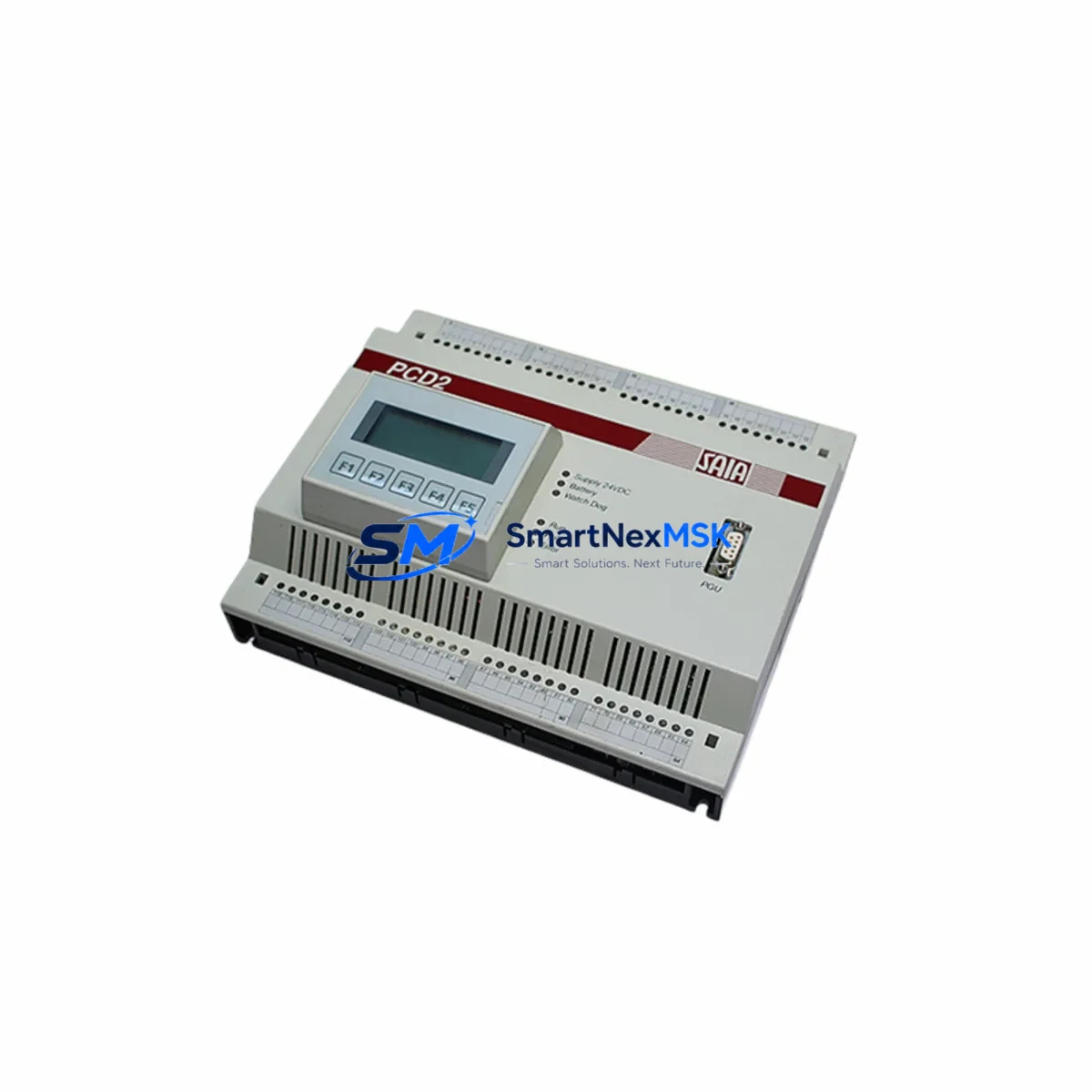
The SAIA PCD2.M110 is a compact, high-reliability CPU module designed for the PCD2 Series programmable logic controller platform developed by SAIA-Burgess Controls. As legacy PCD2 installations reach end-of-service milestones, the PCD2.M110 has become a critical component in retrofit projects, discontinued-part replacements, and control cabinet upgrades across manufacturing, building automation, water treatment, and energy management sectors. Whether you are replacing a failed unit, upgrading an aging control system, or migrating from an earlier PCD2 variant, the PCD2.M110 offers a proven, compatible path forward with minimal disruption to existing program logic and field wiring.
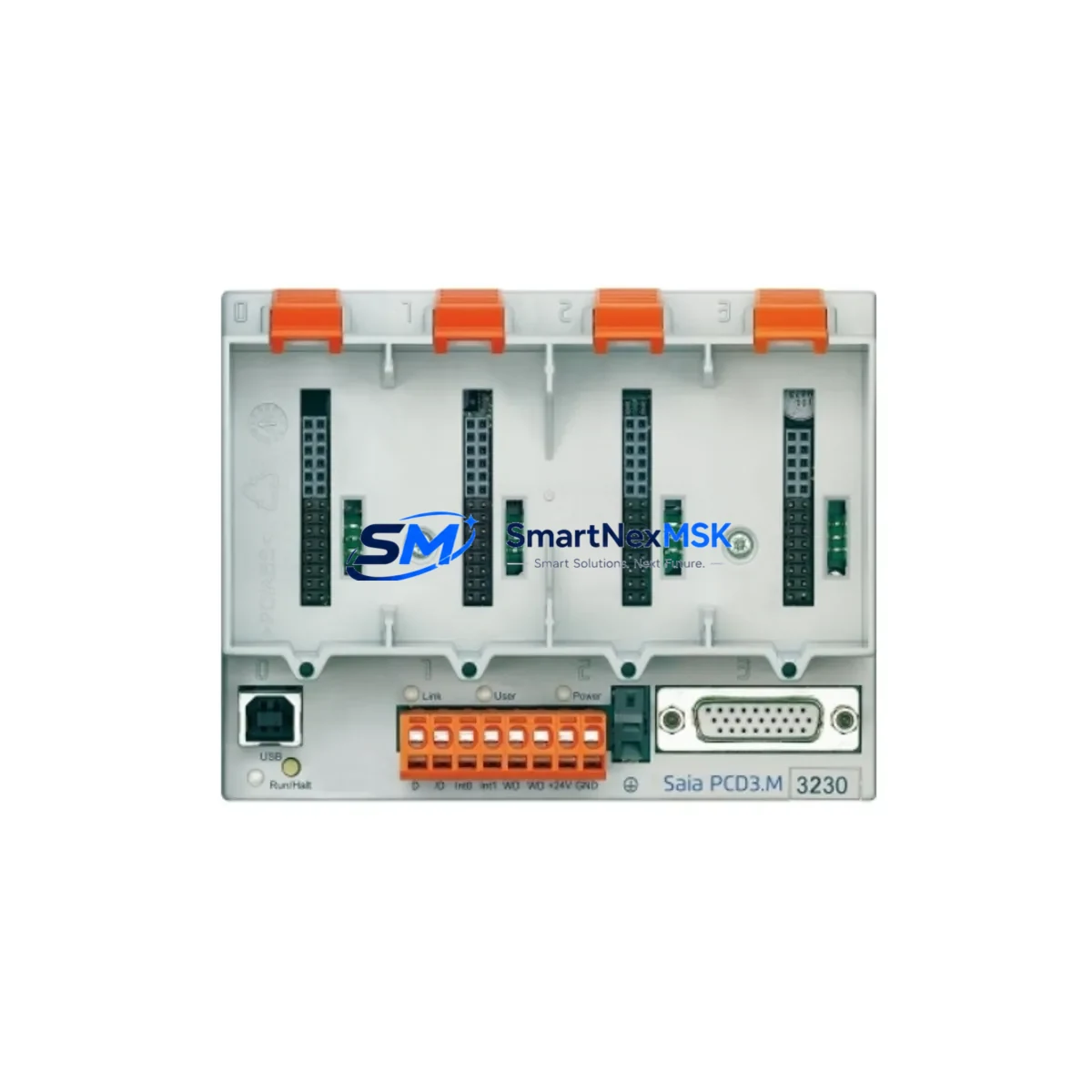
The PCD2.M110 CPU supports the standard PCD2 backplane architecture, making it directly compatible with existing PCD2 rack assemblies and I/O expansion modules already installed in the field. Engineers undertaking a retrofit must verify the power supply module — typically a PCD2.W200 or equivalent — to confirm it can sustain the current draw of the replacement CPU alongside any co-installed communication modules such as the PCD7.F110 Ethernet interface or PCD7.F121 serial gateway. Backplane slot addressing and module order must be preserved to avoid re-mapping I/O channels in the application program.
Before swapping the CPU, technicians should archive the existing PG5 project file and perform a full program upload from the running controller if a current backup is not available. The PCD2.M110 retains compatibility with SAIA PG5 programming software, allowing existing FBD, IL, and ST program blocks to be downloaded without structural modification in most cases. Where the original CPU was an earlier PCD2.M100 or PCD2.M150 variant, minor adjustments to memory allocation or task cycle settings may be required, but the core logic and I/O mapping remain transferable.
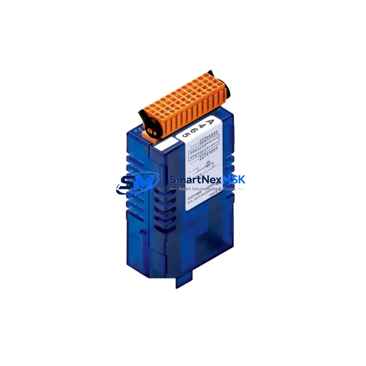
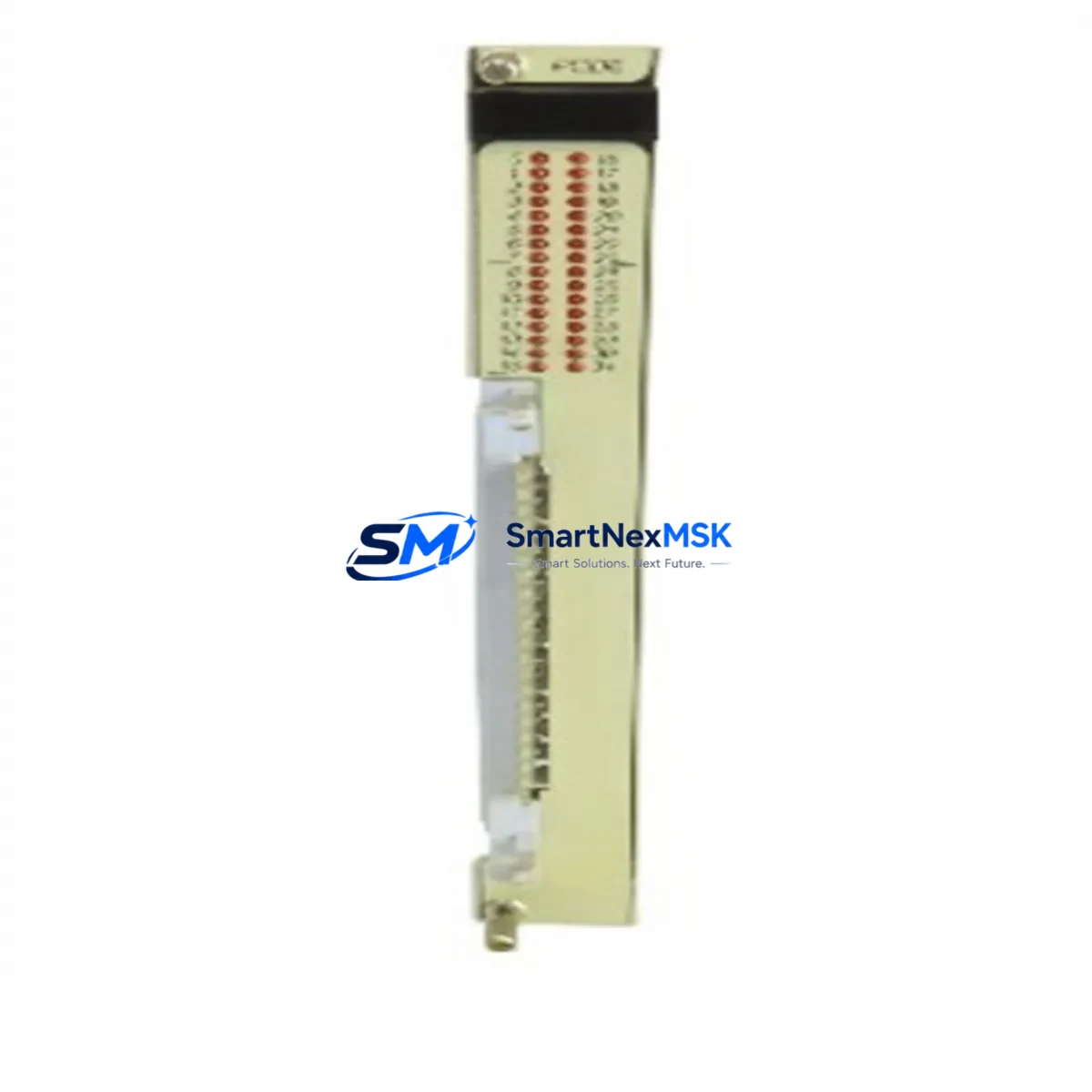
Terminal wiring on the PCD2 platform is handled through dedicated I/O modules rather than the CPU itself, so field wiring to digital input modules such as the PCD2.E110 or analog output modules such as the PCD2.A460 does not need to be disturbed during a CPU swap. This significantly reduces retrofit downtime and eliminates the risk of wiring errors during the changeover. Communication links — including S-Bus, Modbus RTU, and Profibus DP — are managed through co-installed communication modules and are unaffected by the CPU replacement, provided module slot positions are maintained.
For systems that include an HMI panel such as the PCD7.D457 or a third-party operator terminal connected via S-Bus or Modbus, screen variable mappings and communication node addresses should be verified post-swap. In most PCD2 installations, the HMI communicates with the CPU via a fixed node address configured in the PG5 project; as long as this address is preserved in the replacement CPU configuration, HMI screens will resume normal operation without reprogramming.
Commissioning after a PCD2.M110 installation follows a structured sequence: power-off the control cabinet, remove the failed CPU, seat the replacement module firmly into the backplane, restore power, download the verified PG5 project, and perform a cold start. I/O channel status should be confirmed against the process P&ID before releasing the system to automatic operation. Where the system controls critical processes, a parallel test using a PCD2 simulator or a staged hot-standby arrangement with a PCD2.M170 redundancy module is recommended to validate logic execution before full cutover.
SMARTNEXMSK maintains verified stock of the PCD2.M110 and related PCD2 Series components, sourced through authorized industrial distribution channels. Each unit undergoes pre-shipment functional testing and ships with a 12-month warranty covering manufacturing defects and operational failures under normal industrial service conditions. Fast international dispatch from Xiamen ensures short lead times for urgent breakdown replacements and planned maintenance windows alike.
Upgrade Compatibility Table
| Parameter | Detail |
|---|---|
| SKU / Part Number | PCD2.M110 |
| Brand / Manufacturer | SAIA-Burgess Controls |
| Series | PCD2 |
| Module Type | PLC CPU Module |
| Backplane / Rack Compatibility | PCD2 standard backplane; compatible with existing PCD2 rack assemblies |
| Direct Replacement For | PCD2.M100, PCD2.M150 (earlier PCD2 CPU variants) |
| Programming Software | SAIA PG5 (FBD, IL, ST, SFC) |
| Communication Protocols | S-Bus, Modbus RTU, Profibus DP (via co-installed comm modules) |
| I/O Interface | Via PCD2 I/O expansion modules (e.g. PCD2.E110, PCD2.A460) |
| Power Supply Requirement | Verify with installed PCD2.W200 or equivalent PSU |
| HMI Compatibility | PCD7.D457 and S-Bus/Modbus-connected operator panels |
| Installation Type | Backplane slot insertion; no field wiring changes required |
| Commissioning Tool | SAIA PG5 project download via programming cable |
| Warranty | 12 months from date of shipment |
| Origin | Germany (DE) |
| Dispatch Location | Xiamen, China |
Retrofit Planning for Existing Automation Systems
A successful PCD2.M110 retrofit begins with a thorough audit of the existing control cabinet. The installed power supply — commonly a PCD2.W200 24 VDC module — must be assessed for available current headroom, particularly if additional I/O modules such as the PCD2.E110 digital input module or PCD2.A460 analog output module are being added as part of the upgrade scope. Rack capacity should also be reviewed: the standard PCD2 rack accommodates a defined number of module slots, and any planned addition of a PCD7.F110 Ethernet communication module or PCD7.F121 RS-232/RS-485 serial gateway must be accounted for in the slot layout before ordering.
Terminal block wiring connected to existing I/O modules does not need to be disturbed, which is one of the key advantages of a CPU-only swap on the PCD2 platform. Signal cables routed to digital and analog I/O modules remain in place, preserving the integrity of field instrument connections and reducing the risk of mis-wiring during the changeover. Where the retrofit also involves replacing aging I/O modules, the PCD2.E110 and PCD2.A460 maintain the same terminal pitch and connector format as earlier PCD2 I/O variants, simplifying like-for-like substitution.
Communication infrastructure should be mapped prior to the retrofit. S-Bus network topology, Modbus RTU device addresses, and any Profibus DP slave configurations managed through a co-installed PCD7.F150 Profibus module must be documented and verified against the PG5 project before the CPU is replaced. If the system includes a PCD7.D457 HMI or a third-party SCADA connection, communication node addresses and variable tag mappings should be confirmed to ensure seamless resumption of supervisory functions after the CPU swap.
Where the retrofit scope extends to replacing a programming cable or updating the PC-side interface, the standard SAIA PCD programming cable compatible with PG5 should be sourced alongside the CPU module to avoid delays during on-site commissioning. Having the correct cable and a pre-tested PG5 project file ready before the maintenance window opens is essential for keeping the retrofit within the planned downtime budget.
Downtime Control During System Migration
Minimizing production downtime during a PCD2.M110 swap requires preparation that begins well before the maintenance window. The most effective approach is to upload and verify the running program from the existing CPU in advance, confirm it compiles and simulates correctly in PG5, and stage the replacement module with the project pre-loaded where the process allows an offline download. This eliminates the program transfer step from the critical path on the day of the swap.
During the changeover itself, the sequence should be: controlled process shutdown, CPU removal, PCD2.M110 installation into the backplane, power restoration, program download confirmation, I/O channel verification, and controlled process restart. The entire sequence on a well-prepared PCD2 system typically takes under two hours for an experienced controls engineer, with the majority of time spent on I/O verification and process restart checks rather than the physical module swap.
To protect original program logic, the PG5 project archive should be stored in at least two locations — a local engineering workstation and a secure network share — before any work begins. If the system uses S-Bus multi-master communication with other PCD2 or PCD1 controllers on the same network segment, the node address of the replacement CPU must be set identically to the original to prevent communication faults on peer controllers during restart. Retaining the original CPU as a tested spare for a defined period after the retrofit provides an additional safety net during the post-commissioning observation phase.
Retrofit Support FAQ
Q: Is the PCD2.M110 a direct drop-in replacement for the PCD2.M100?
A: In most installations, yes. The PCD2.M110 uses the same backplane connector and slot format as the PCD2.M100. Minor PG5 project adjustments related to memory configuration may be required depending on the original project structure, but field wiring and I/O module positions are unaffected.
Q: Do I need to re-commission my HMI after replacing the CPU?
A: Not typically. If the S-Bus or Modbus node address of the replacement CPU matches the original, HMI panels such as the PCD7.D457 will resume communication automatically after the CPU restarts. Variable tag mappings and screen logic do not need to be modified.
Q: What pre-shipment testing is performed on the PCD2.M110?
A: Each PCD2.M110 unit dispatched by SMARTNEXMSK undergoes functional power-on testing and basic I/O communication verification before shipment. Units are shipped with a 12-month warranty covering manufacturing defects and operational failures under normal industrial service conditions.
Q: Can the PCD2.M110 support Profibus DP communication?
A: Profibus DP on the PCD2 platform is handled through a dedicated co-installed communication module such as the PCD7.F150 Profibus DP interface, not the CPU itself. The PCD2.M110 is fully compatible with this architecture; the Profibus configuration in the PG5 project is retained without modification when the CPU is replaced.
© 2026 SMARTNEXMSK. All rights reserved.
Original Source: https://smartnexmsk.com
Contact: sales@smartnexmsk.com | +86 18259474341