SAIA PCD6.A4 Retrofit-Ready CPU Module for PCD6 Series Control Systems
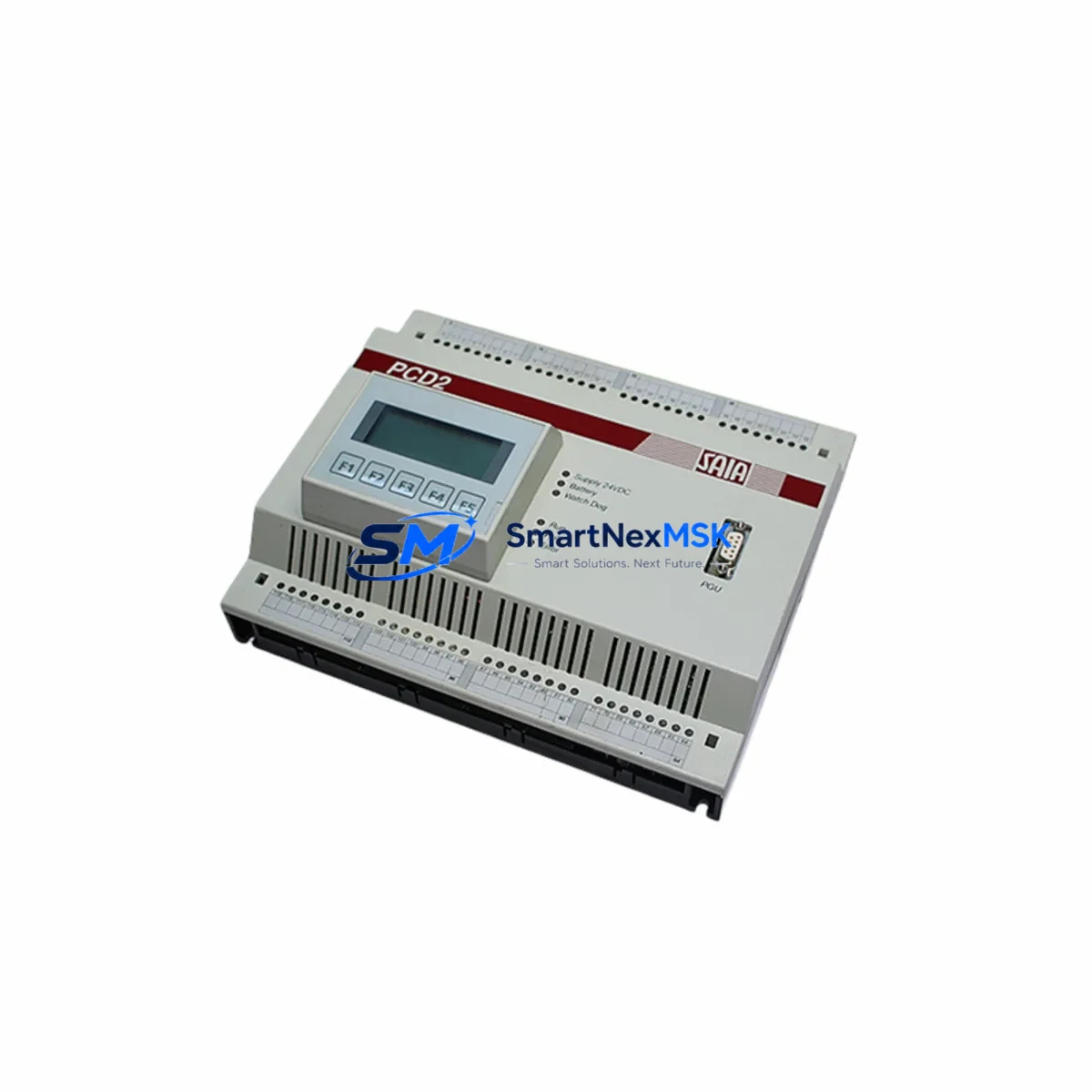
The SAIA PCD6.A4 is a high-performance CPU module engineered for seamless integration into existing SAIA PCD6 Series programmable logic controller platforms. Designed with legacy system modernization in mind, this module serves as a direct retrofit solution for facilities operating aging PCD6 control cabinets that require CPU replacement, capacity expansion, or platform stabilization without a full system overhaul. Whether your plant is recovering from an unplanned CPU failure, executing a scheduled control system upgrade, or migrating from an end-of-life SAIA PCD4 or PCD2 platform, the PCD6.A4 provides a technically validated, cost-effective path forward.
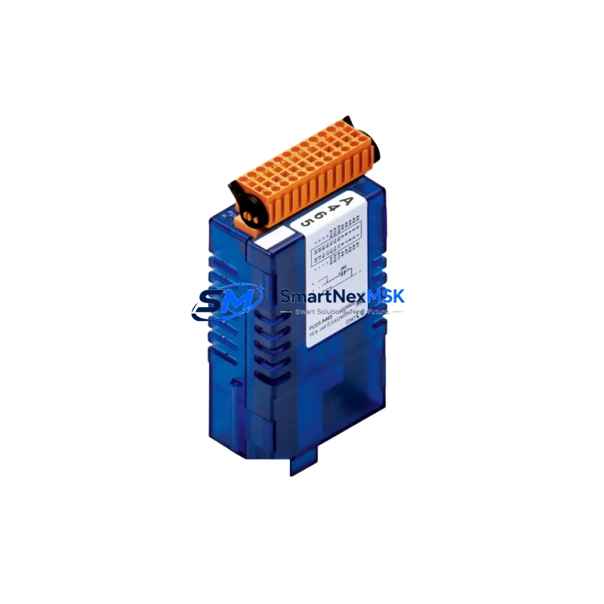
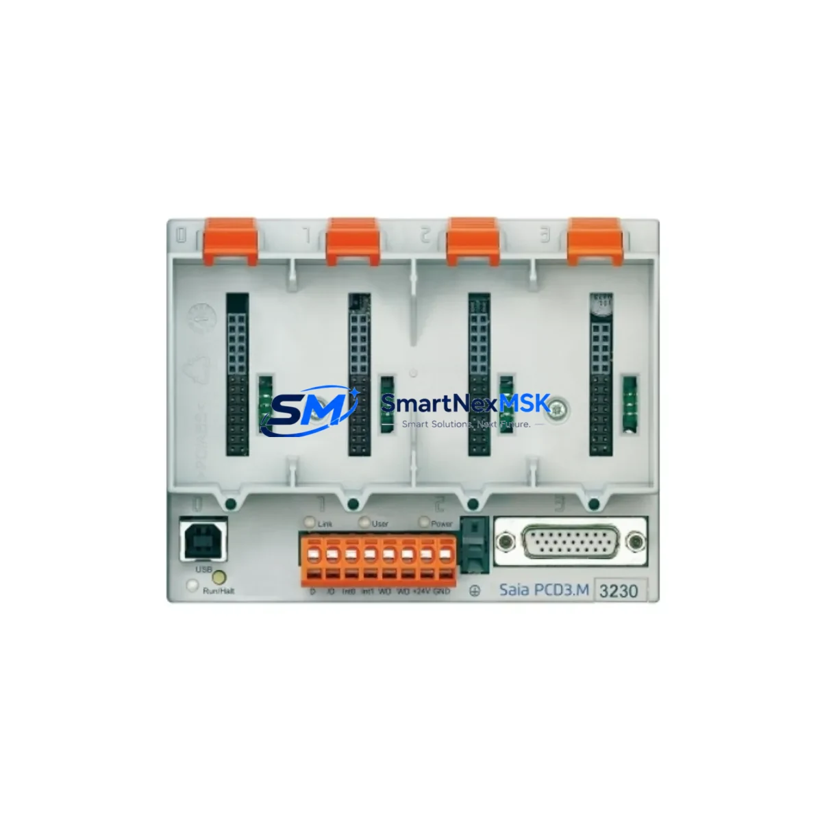
The PCD6.A4 CPU module slots directly into the PCD6 backplane rack, maintaining full compatibility with the existing I/O bus architecture. Engineers undertaking a retrofit must verify the backplane slot assignment and confirm that the module address configuration matches the original CPU addressing scheme used in the SAIA PG5 project file. Where the original system used a PCD6.C200 or PCD6.C150 CPU, the PCD6.A4 offers an upgrade path with expanded memory and enhanced instruction throughput, while preserving the original program logic structure and retaining compatibility with existing PCD6.E100 digital input modules and PCD6.A400 analog output modules already installed in the rack.
Power supply compatibility is a critical checkpoint during any PCD6 retrofit. The PCD6.W500 power supply module must be verified to deliver sufficient current capacity for the upgraded CPU alongside all co-installed I/O modules. In systems where the original power budget was calculated for an older, lower-consumption CPU, a power audit is strongly recommended before commissioning the PCD6.A4. Terminal wiring on the backplane connector follows the standard PCD6 pinout, and no rewiring of field I/O terminals is required when replacing a same-generation CPU module.
For facilities running PROFIBUS-DP networks, the PCD6.A4 supports native PROFIBUS master and slave operation, ensuring continuity of communication with field devices such as remote I/O stations, variable frequency drives, and third-party sensors already integrated into the control network. Sites migrating from serial RS-232 or RS-485 communication links to Ethernet-based protocols will find the PCD6.A4’s onboard Ethernet port a significant advantage, enabling direct integration with SCADA systems, HMI panels, and MES platforms via Modbus TCP or SAIA S-Bus over Ethernet. Where legacy PCD7.D457 operator panels or PCD7.D230 HMI terminals are in service, communication link reconfiguration in the PG5 project is required to map the new CPU’s communication port assignments correctly.
During the retrofit planning phase, engineers should export and archive the complete PG5 project from the existing CPU before removal. The compiled program, symbol table, and hardware configuration must be validated against the PCD6.A4’s firmware version to confirm instruction set compatibility. In most PCD6 retrofit scenarios, the existing ladder logic or FBD program compiles without modification; however, any use of CPU-specific system flags or hardware-dependent function blocks should be reviewed against the PCD6.A4 technical datasheet. After loading the program, a full I/O force test and loop check should be conducted prior to returning the system to automatic operation.
All PCD6.A4 modules supplied by SMARTNEXMSK are sourced from verified industrial supply channels, individually tested for functional integrity prior to dispatch, and covered by a 12-month warranty against manufacturing defects and operational failure. Stock availability is maintained to support both emergency breakdown replacements and planned maintenance schedules. Global shipping is available with lead times confirmed at order placement.
Upgrade Compatibility Table
| Parameter | Detail |
|---|---|
| Module SKU | PCD6.A4 |
| Brand / Manufacturer | SAIA-Burgess (Saia-Burgess Controls AG) |
| Series | SAIA PCD6 |
| Module Type | CPU Module (Central Processing Unit) |
| Backplane / Rack Compatibility | PCD6 Series backplane rack; standard slot installation |
| Communication Interfaces | Ethernet (Modbus TCP / S-Bus), PROFIBUS-DP, RS-232/RS-485 |
| Replaces / Upgrades From | PCD6.C200, PCD6.C150, and equivalent PCD6 Series CPUs |
| I/O Module Compatibility | Compatible with PCD6.E100, PCD6.A400, and standard PCD6 I/O range |
| Power Supply Requirement | Verify PCD6.W500 current capacity before installation |
| Programming Software | SAIA PG5 (verify firmware compatibility with project version) |
| HMI Compatibility | PCD7.D457, PCD7.D230 and compatible SAIA operator panels |
| Installation Type | Direct backplane slot insertion; no field wiring changes required |
| Commissioning Requirement | I/O force test, loop check, and program reload verification |
| Origin | Switzerland (CH) |
| Warranty | 12 Months — covers manufacturing defects and operational failure |
| Pre-Shipment Testing | Functional integrity test performed on every unit before dispatch |
Retrofit Planning for Existing Automation Systems
A successful PCD6.A4 retrofit begins with a thorough audit of the existing control cabinet. Start by documenting the current rack layout, noting the slot positions of all installed modules including the PCD6.W500 power supply, the existing CPU, any PCD6.E100 digital input modules, PCD6.A400 analog output modules, and any installed PCD6.N100 or PCD6.N200 communication modules. Photograph all terminal wiring and label each field cable before any module is removed.
Where the system includes a PCD7.D457 or PCD7.D230 HMI panel, verify that the HMI communication driver and tag database are backed up independently of the CPU program. HMI screen layouts and tag mappings are typically stored on the panel itself or on a connected engineering workstation, but confirming this before the retrofit prevents loss of operator interface configuration. If the HMI communicates via S-Bus serial, the new CPU’s serial port parameters must be configured to match the existing baud rate and station address settings.
For systems integrating PROFIBUS-DP remote I/O racks or third-party field devices, the GSD file configuration within the PG5 hardware configurator must be preserved and reloaded to the PCD6.A4 after installation. Any PCD6.N100 PROFIBUS communication modules co-installed in the rack will continue to operate normally, as the PCD6.A4 maintains full compatibility with the PCD6 backplane communication bus. Similarly, any PCD6.T100 timer or counter modules installed in adjacent slots will retain their configuration without modification.
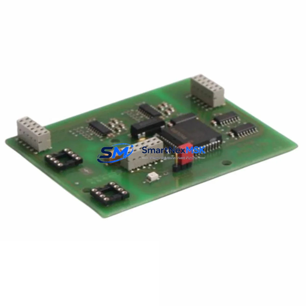
Engineers should also verify the module address DIP switch settings on the PCD6.A4 before installation. The CPU module address must match the address defined in the PG5 hardware configuration file. Mismatched addressing is one of the most common causes of post-retrofit communication faults and can be resolved quickly during bench testing before the module is installed in the live cabinet. A PCD programming cable (USB or serial type, compatible with PG5) should be on hand during commissioning to allow direct CPU connection for program upload, online monitoring, and fault diagnostics.
Downtime Control During System Migration
Minimizing production downtime during a PCD6 CPU replacement requires a structured pre-outage preparation process. Before the scheduled maintenance window, complete the following steps: export and verify the PG5 project from the existing CPU, confirm the PCD6.A4 module address configuration, prepare a tested programming cable and laptop with PG5 installed, and brief the operations team on the expected outage duration and restart sequence.
During the outage, the physical CPU swap on a PCD6 backplane typically takes under 15 minutes for an experienced engineer. The majority of retrofit time is consumed by program reload, I/O verification, and communication link confirmation. To protect the original program logic, never overwrite the archived PG5 project during the retrofit — work from a copy. If the system uses battery-backed data retention for process setpoints or counters, verify that the PCD6.A4’s onboard battery is charged and that data retention blocks are correctly mapped in the program before restarting in automatic mode.
Where continuous process control is required and a cold restart is not acceptable, consider a staged migration approach: install and configure the PCD6.A4 in a parallel test rack using a duplicate program, validate all I/O responses and communication links offline, then execute the live swap during the shortest available maintenance window. This approach is particularly effective in facilities where the PCD6 system controls critical utilities, HVAC, or safety-related interlocks that cannot tolerate extended downtime.
Retrofit Support FAQ
Q1: Is the PCD6.A4 a direct drop-in replacement for the PCD6.C200 CPU?
The PCD6.A4 installs into the same backplane slot and uses the same PCD6 rack interface as the PCD6.C200. In most retrofit scenarios, the existing PG5 program compiles and runs without modification. Engineers should review any CPU-specific system flags or hardware function blocks in the original program against the PCD6.A4 datasheet to confirm full instruction compatibility before going live.
Q2: Does the PCD6.A4 require any terminal rewiring during installation?
No field terminal rewiring is required. The PCD6.A4 connects to the system via the backplane bus connector, and all field I/O wiring remains on the existing I/O modules. Only the CPU module itself is replaced. Verify that the backplane connector pins are clean and undamaged before inserting the new module.
Q3: What communication protocols does the PCD6.A4 support for SCADA and HMI integration?
The PCD6.A4 supports Modbus TCP, SAIA S-Bus over Ethernet, PROFIBUS-DP, and serial S-Bus (RS-232/RS-485). This covers the majority of SCADA and HMI integration requirements in existing PCD6 installations, including legacy PCD7.D457 panels and modern Ethernet-connected supervisory systems.
Q4: What warranty and pre-shipment testing is provided with the PCD6.A4?
Every PCD6.A4 unit supplied by SMARTNEXMSK undergoes a functional integrity test prior to dispatch to verify module operation, communication port functionality, and backplane interface integrity. All units are covered by a 12-month warranty against manufacturing defects and operational failure from the date of delivery. Warranty claims are processed directly through our technical support team.
© 2026 SMARTNEXMSK. All rights reserved.
Original Source: https://smartnexmsk.com
Contact: sales@smartnexmsk.com | +86 18259474341