Schneider 140ACO13000 Retrofit-Ready Analog Output Module for Quantum Control Systems
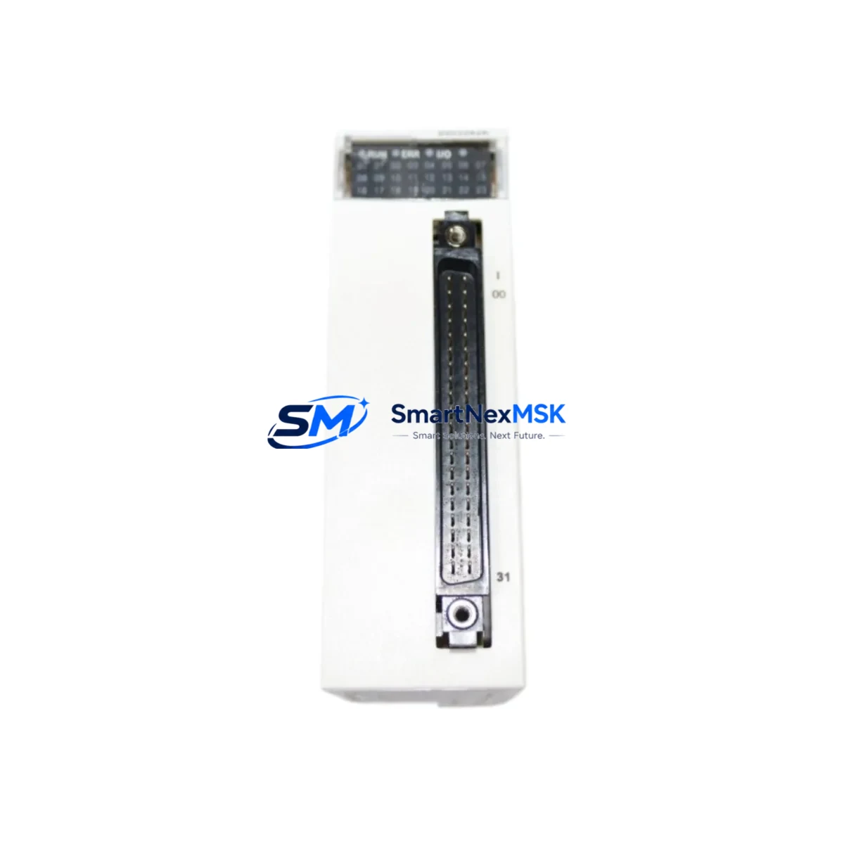
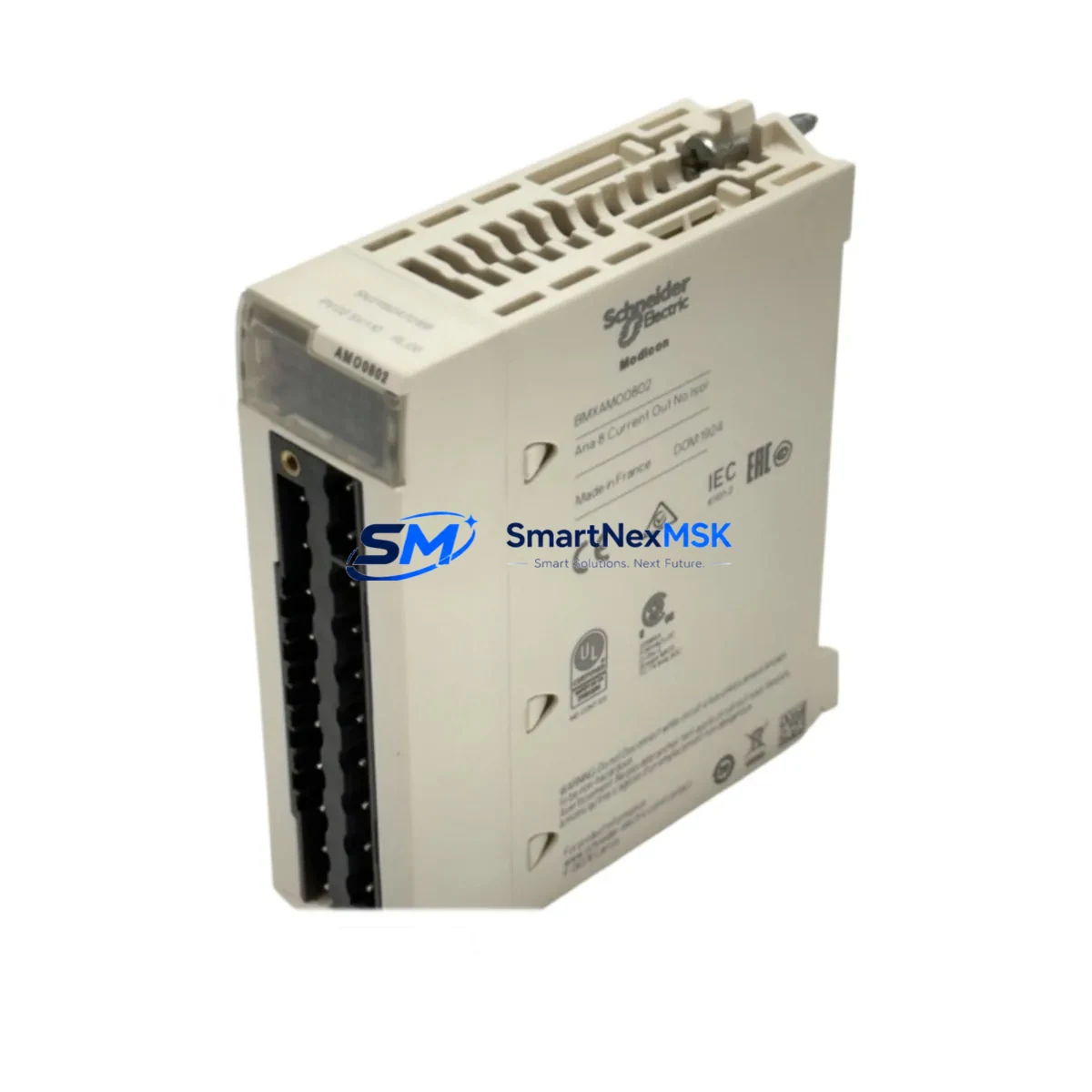
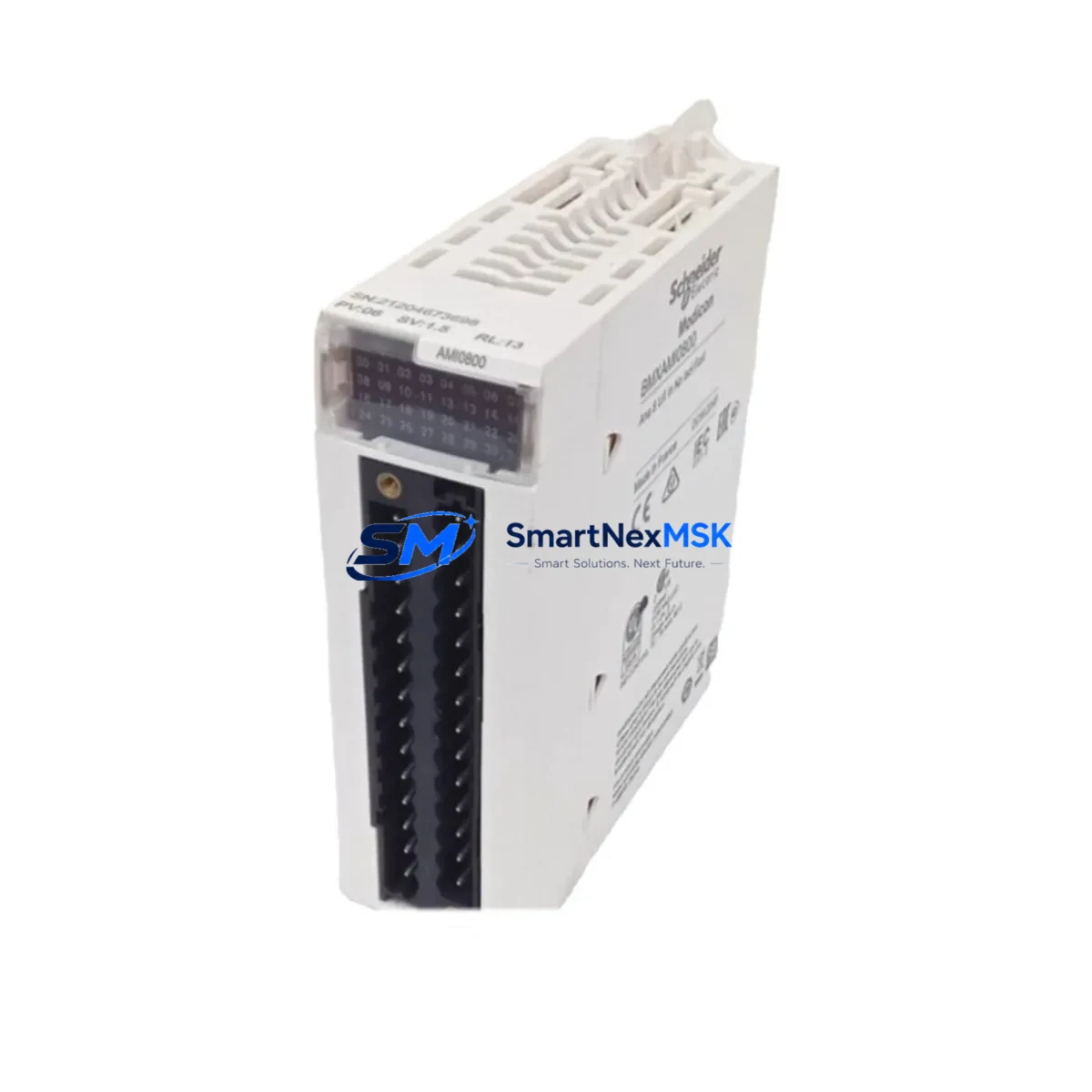
The Schneider Electric 140ACO13000 is an 8-channel, 12-bit analog output module engineered for the Modicon Quantum automation platform. As legacy Quantum-series control systems approach end-of-life or require capacity expansion, the 140ACO13000 remains one of the most sought-after retrofit components for engineers managing brownfield upgrades, partial panel replacements, and phased migration projects. Whether you are replacing a failed unit on a running production line or modernizing an aging DCS architecture, this module delivers the signal fidelity, backplane compatibility, and firmware transparency that Quantum-based systems demand.
Each unit shipped by SMARTNEXMSK undergoes pre-shipment functional verification, including channel-by-channel output calibration checks across the 4–20 mA and 0–10 V DC ranges. Modules are supplied with a 12-month warranty covering manufacturing defects and functional failures under normal operating conditions. Stock is maintained for immediate dispatch, minimizing procurement lead times for urgent maintenance and unplanned downtime scenarios.
Upgrade Compatibility Table
| Parameter | 140ACO13000 Specification | Retrofit Notes |
|---|---|---|
| Output Channels | 8 channels, individually configurable | Direct replacement for 140ACO02000 (4-CH); verify I/O address mapping in Unity Pro / Concept |
| Resolution | 12-bit (0–4095 counts) | Matches legacy Quantum analog output resolution; no scaling changes required in most applications |
| Output Signal Types | 4–20 mA / 0–10 V DC (per channel) | Confirm field wiring terminal assignments; 140XTS00200 terminal block recommended for clean retrofit |
| Backplane Interface | Modicon Quantum backplane (140 series) | Compatible with 140CRA93100, 140CRP93100 remote I/O heads; verify slot addressing in rack configuration |
| Communication Protocol | Modbus RTU / Modbus TCP (via NOE/NOM modules) | No protocol migration required; existing 140NOE77101 or 140NOM21100 communication modules remain in service |
| Power Consumption | ≤ 3.5 W (backplane) | Verify rack power budget via 140CPS11420 or 140CPS21400 power supply capacity before installation |
| Installation Format | Single-slot Quantum rack module | Compatible with 140XBP01600 (16-slot) and 140XBP00600 (6-slot) backplanes |
| Replacement Path | Replaces 140ACO02000, 140ACO13000 (same SKU restock), legacy Modicon 800-series analog outputs | Unity Pro variable mapping preserved if slot number unchanged; full re-download not required in most cases |
| Commissioning Tool | Unity Pro XL / Concept 2.6+ | Use 140USB31100C programming cable or 140NOM21100 for online diagnostics post-installation |
| Warranty | 12 months from shipment date — covers functional failure and manufacturing defects under normal operating conditions | |
Retrofit Planning for Existing Automation Systems
Successful integration of the 140ACO13000 into an existing Quantum control system begins well before the module arrives on site. Engineers should start by auditing the current rack configuration using Unity Pro’s I/O configuration editor or the legacy Concept software, confirming the slot address, module type declaration, and any associated DDT (Derived Data Type) structures tied to the outgoing analog output module.
Power budget verification is a critical pre-installation step. The 140CPS11420 or 140CPS21400 power supply modules feeding the rack must have sufficient headroom to support the 140ACO13000’s backplane draw alongside existing modules such as the 140ACI04000 analog input module, 140DDO35300 discrete output module, and any installed 140NOE77101 Ethernet communication module. A rack power audit using the Quantum Power Calculator tool prevents post-installation instability.
Terminal wiring is the next focus area. The 140ACO13000 uses a 140XTS00200 removable terminal block, which allows field wiring to be disconnected from the module without disturbing individual conductors — a significant advantage during hot-swap scenarios on partially live panels. Technicians should label and photograph all existing terminal connections before removal of the legacy module, particularly where 4–20 mA loops feed downstream instruments such as variable frequency drives, control valves, or SCADA analog inputs.
For systems running 140NOM21100 Modbus serial communication modules or 140CRP93100 remote I/O head adapters, no protocol reconfiguration is required. The 140ACO13000 presents identically to its predecessor on the Modbus register map, provided the slot address is preserved. Where the rack also hosts a 140CPU65160 or 140CPU67160 processor module, engineers should confirm that the Unity Pro project file reflects the correct module type in the hardware configuration tree before performing an online program download.
HMI screens connected via Magelis XBTGT or third-party SCADA systems reading analog output setpoints over Modbus TCP should be validated post-installation using a loop calibrator to confirm that register values translate correctly to field signal levels. This step is especially important when replacing a module that had accumulated calibration offsets over years of service.
Downtime Control During System Migration
Minimizing production downtime during a Quantum analog output module replacement requires a structured sequence that protects both the control program and the physical process. The recommended approach is to place the affected control loop in manual mode at the DCS or SCADA level before initiating any hardware work, transferring setpoint authority to the operator station or a local manual station on the field instrument.
With the loop in manual, the 140ACO13000 can be removed and replaced without triggering process upsets. Because the module occupies a single backplane slot and uses a removable terminal block, physical swap time is typically under ten minutes for a prepared technician. The 140USB31100C programming cable connected to the 140CPU65160 processor allows Unity Pro to perform an online configuration update — pushing the new module type declaration to the CPU without a full program stop — provided the replacement module is the same SKU and the slot address is unchanged.
After the module is seated and the terminal block reconnected, bring the output channels online one at a time using Unity Pro’s animation table or the module’s built-in diagnostic LEDs. Verify each channel’s output against the expected engineering unit value before returning the loop to automatic control. For multi-loop panels where several 140ACO13000 modules are being replaced in a single maintenance window, stagger the channel verification sequence to avoid simultaneous setpoint steps that could stress downstream actuators.
Document the as-found and as-left calibration readings for each channel, and retain the Unity Pro project backup taken immediately before the swap. This record supports both internal maintenance logs and any future audit requirements under ISO 9001 or IEC 62443 compliance frameworks.
Retrofit Support FAQ
Q1: Is the 140ACO13000 a direct drop-in replacement for the 140ACO02000?
The 140ACO13000 (8-channel) is not pin-for-pin identical to the 140ACO02000 (4-channel), but it is backplane-compatible and can replace it in the same slot. The additional four channels will appear as unused I/O in the Unity Pro configuration unless the program is updated to utilize them. Terminal block wiring must be reviewed, as the 140ACO13000 uses all 8 channel terminals versus the 4-channel layout of the 140ACO02000.
Q2: Do I need to perform a full program download after replacing the module?
In most cases, no. If the replacement module is the same SKU (140ACO13000 for 140ACO13000) and the slot address is unchanged, Unity Pro can perform an online configuration update without stopping the CPU. A full download is required only if the hardware configuration tree is modified or if the processor is in Stop mode during the swap. Always back up the current project before any hardware change.
Q3: What pre-shipment testing does SMARTNEXMSK perform on the 140ACO13000?
Each module undergoes channel-by-channel output verification across both the 4–20 mA and 0–10 V DC ranges prior to shipment. Functional test results are available upon request. All units are covered by a 12-month warranty from the shipment date, covering manufacturing defects and functional failures under normal operating conditions.
Q4: Can the 140ACO13000 operate in a remote I/O rack connected via 140CRP93100?
Yes. The 140ACO13000 is fully compatible with Quantum remote I/O configurations using the 140CRA93100 remote I/O adapter and 140CRP93100 remote I/O head. Ensure that the remote drop’s power supply (typically a 140CPS11420) has sufficient capacity for the module’s backplane load, and verify the remote drop address and slot mapping in the Unity Pro hardware configuration before commissioning.
© 2026 SMARTNEXMSK. All rights reserved.
Original Source: https://smartnexmsk.com
Contact: sales@smartnexmsk.com | +86 18259474341