Schneider CAD32MD Retrofit-Ready Auxiliary Relay for TeSys Control Systems
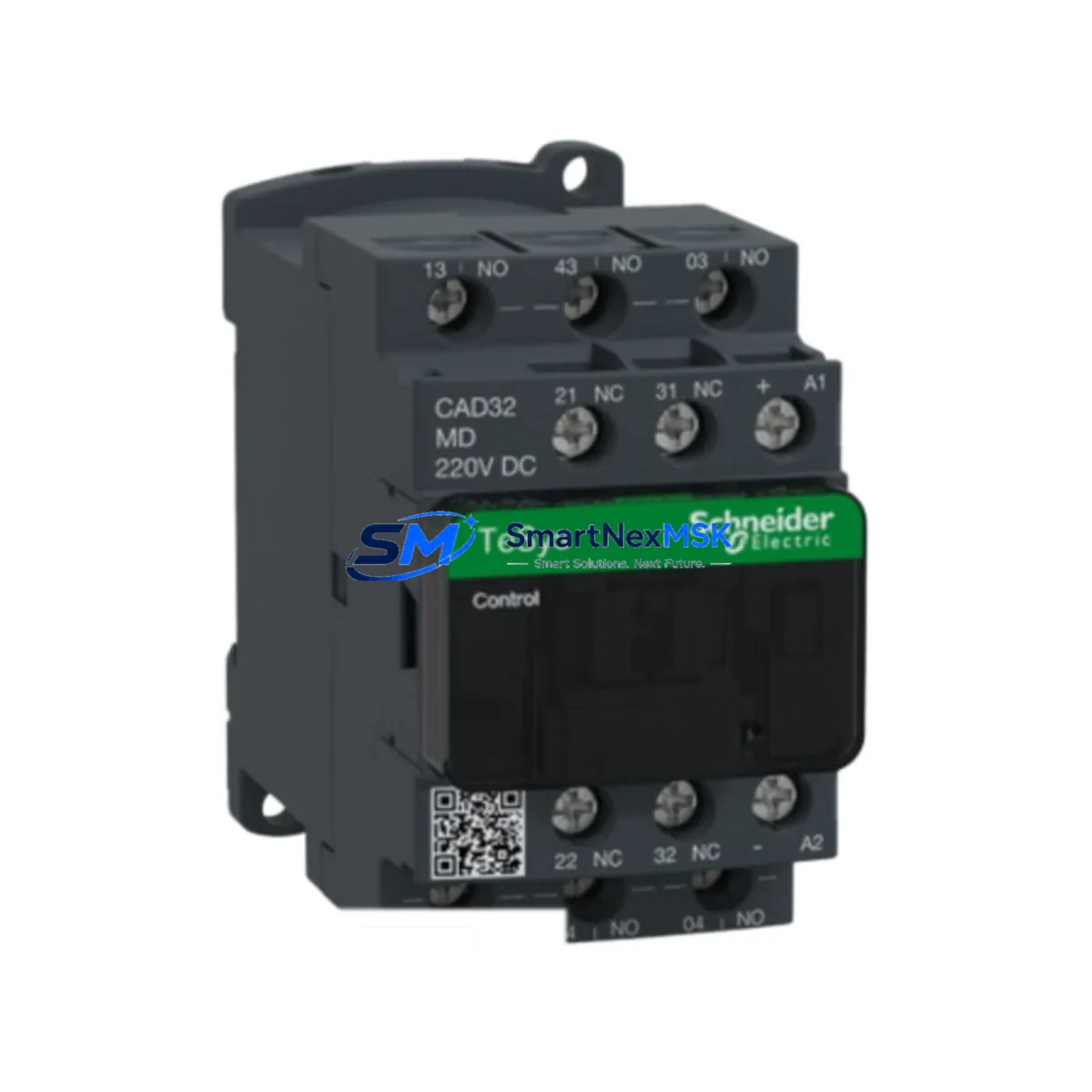
The Schneider Electric CAD32MD is a 3NO+2NC auxiliary control relay rated at 220V DC, purpose-built for integration into TeSys series motor control and protection systems. As legacy automation lines age and original components reach end-of-life, the CAD32MD has become a critical retrofit solution for engineers managing control cabinet upgrades, partial panel replacements, and system modernization projects where full platform migration is not yet feasible or cost-effective.
This relay is a direct drop-in replacement for discontinued auxiliary relay variants within the TeSys D and TeSys K families. Its standardized A1/A2 coil terminal layout and front-face contact block configuration ensure compatibility with existing DIN rail mounting arrangements and terminal wiring schemes without requiring panel re-engineering. Engineers retrofitting older Schneider LC1D contactor assemblies or replacing failed CAD32 variants in legacy motor starter circuits will find the CAD32MD fully interchangeable in both mechanical footprint and electrical interface.
Upgrade Compatibility Table
| Parameter | CAD32MD Specification | Retrofit Notes |
|---|---|---|
| Contact Configuration | 3NO + 2NC | Verify existing wiring diagram before substitution |
| Coil Voltage | 220V DC | Confirm DC supply rail; do not substitute AC coil variants |
| Mounting | DIN rail / panel mount | Compatible with standard 35mm DIN rail in TeSys enclosures |
| Terminal Type | Screw clamp, A1/A2 coil | Match terminal torque spec (1.7 N·m) per original wiring |
| Communication Compatibility | Hardwired I/O only | No fieldbus interface; integrate via discrete I/O to PLC |
| Replacement Path | CAD32, CAD32B7, CAD32F7 | Cross-reference coil voltage suffix before ordering |
| Warranty | 12 Months | Covers manufacturing defects; includes pre-shipment functional test |
Retrofit Planning for Existing Automation Systems
When integrating the CAD32MD into an existing control system, the retrofit scope typically extends beyond the relay itself. In a typical TeSys-based motor control center (MCC), the CAD32MD operates alongside LC1D series contactors, LRD thermal overload relays, and GV2 motor circuit breakers — all of which must be verified for continued compatibility during the upgrade. Engineers should audit the existing control cabinet layout to confirm that the 24V or 220V DC auxiliary supply rail feeding the relay coil is correctly sized and protected, particularly when multiple auxiliary relays share a common power bus.
For systems where the CAD32MD interfaces with a Modicon M340 or Modicon M580 PLC, discrete I/O modules such as the BMX DDI 1602 or BMX DDO 1602 are commonly used to read contact status and issue coil energization commands. Confirm that the PLC I/O module’s input voltage range matches the relay’s output contact rating to avoid signal mismatch. Where the control system uses a Magelis HMI panel for operator interface, verify that the associated HMI screen logic references the correct memory bit addresses mapped to the relay’s I/O points — stale address mappings from the original relay model are a common source of commissioning errors during retrofit.
In installations using Modbus RTU or CANopen communication backbones, the CAD32MD’s hardwired contacts must be wired to a compatible remote I/O module — such as a TM3 expansion module or an OTB 1E0 distributed I/O block — to maintain supervisory visibility from the SCADA or DCS layer. Ensure that the remote I/O module’s firmware and configuration file are updated to reflect the new relay’s wiring topology before energizing the panel. Where the original system used a TSX Micro or TSX Premium PLC, the retrofit may also require updating the Unity Pro or PL7 Pro program to reassign I/O addresses if the relay’s physical slot position has changed.
All replacement units are pre-tested prior to shipment. Stock is maintained for immediate dispatch, supporting urgent breakdown recovery and planned maintenance windows alike. 12-month warranty is included as standard.
Downtime Control During System Migration
Minimizing production downtime during a relay retrofit requires careful pre-staging and a structured switchover sequence. Before removing the failed or obsolete CAD32 relay, photograph the existing terminal wiring and record all wire labels, ferrule numbers, and contact assignments. This documentation serves as the reference baseline for re-termination and post-installation verification.
Where possible, pre-wire the CAD32MD on a temporary terminal block outside the live panel and perform a bench-level continuity check against the original wiring diagram. This allows the physical swap to be completed within a single planned maintenance window — typically under 30 minutes for a single relay replacement — without requiring extended panel de-energization. After installation, perform a step-by-step functional test: energize the coil at rated voltage, verify contact state changes on all five poles using a multimeter or the PLC’s I/O diagnostic screen, and confirm that the HMI operator panel reflects the correct relay status before returning the circuit to automatic mode.
For systems with redundant control paths, consider keeping the original relay in a de-energized bypass state during the initial commissioning period to allow rapid fallback if unexpected behavior is observed. Once the CAD32MD has completed a full operational cycle under normal load conditions, the bypass can be removed and the panel restored to its standard configuration.
Retrofit Support FAQ
Q: Is the CAD32MD a direct replacement for the CAD32B7 and CAD32F7?
A: The CAD32MD shares the same contact configuration (3NO+2NC) and mechanical footprint as the CAD32B7 and CAD32F7, but differs in coil voltage — MD denotes 220V DC. Always verify the coil voltage suffix of the original relay before substituting to avoid coil burnout or non-operation.
Q: What wiring changes are required when retrofitting the CAD32MD into an existing panel?
A: In most cases, no wiring changes are required if the original relay was a same-voltage CAD32 variant. Re-terminate A1/A2 coil wires and contact wires to the corresponding terminals on the CAD32MD, following the original wiring diagram. Torque all screw terminals to 1.7 N·m and perform a continuity check before energizing.
Q: How is compatibility with the connected PLC or DCS verified before commissioning?
A: After installation, use the PLC’s I/O diagnostic function (e.g., Unity Pro I/O viewer or Modicon M580 DTM browser) to confirm that each contact state change on the CAD32MD is correctly reflected in the controller’s input image table. Cross-reference against the original I/O mapping document and update any address assignments if the relay’s physical location has changed.
Q: What does the 12-month warranty cover?
A: The 12-month warranty covers manufacturing defects in materials and workmanship. Each unit undergoes a pre-shipment functional test verifying coil energization, contact continuity, and insulation resistance. Warranty claims are processed with priority turnaround to minimize impact on production operations.
© 2026 SMARTNEXMSK. All rights reserved.
Original Source: https://smartnexmsk.com
Contact: sales@smartnexmsk.com | +86 18259474341