Schneider 140ARI03010 Retrofit-Ready RTD Analog Input for Modicon Quantum Control Systems
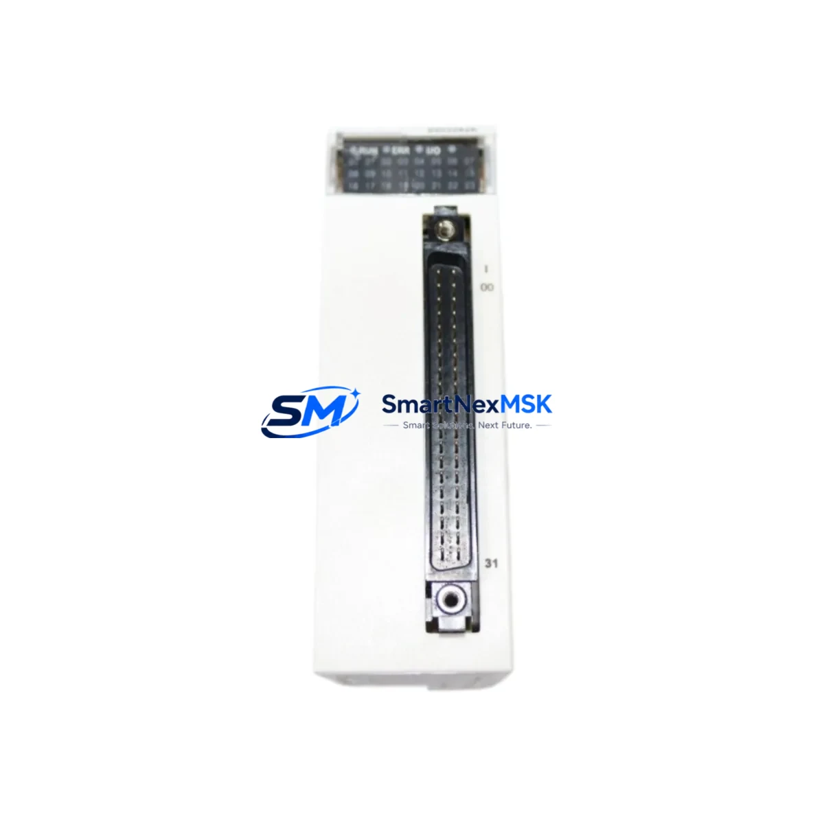
The Schneider Electric 140ARI03010 is an 8-channel RTD (Resistance Temperature Detector) analog input module engineered for the Modicon Quantum PLC platform. As legacy Quantum systems approach end-of-life and spare parts become increasingly scarce, the 140ARI03010 remains one of the most sought-after retrofit components for plants running continuous process control, HVAC automation, and temperature-critical manufacturing lines. SMARTNEXMSK maintains verified stock of this module with full functional testing, 12-month warranty coverage, and rapid global dispatch to minimize your plant downtime.
Whether you are replacing a failed module in an existing Quantum rack, upgrading from an older 140ARI03000 variant, or consolidating a multi-rack control cabinet during a broader DCS migration, the 140ARI03010 delivers the signal accuracy and backplane compatibility your system demands. Each unit shipped by SMARTNEXMSK undergoes pre-shipment functional verification to confirm channel integrity, backplane communication, and firmware readiness before leaving our facility.
Upgrade Compatibility Table
| Parameter | 140ARI03010 Specification | Retrofit Notes |
|---|---|---|
| Input Channels | 8 x RTD (PT100, PT1000, Ni100, Cu10) | Verify sensor type matches existing field wiring |
| Backplane Interface | Modicon Quantum 800-series backplane | Compatible with 140XBP00400 / 140XBP01000 / 140XBP01600 racks |
| Module Slot | Any I/O slot in Quantum rack | Confirm slot address in Unity Pro / Concept software before swap |
| Power Consumption | 800 mA @ 5 VDC (backplane) | Verify 140CPS11420 or 140CPS21400 power supply capacity |
| Wiring Compatibility | 2-wire / 3-wire / 4-wire RTD | Retain existing terminal block wiring; confirm lead resistance compensation |
| Communication | Modbus Plus / Ethernet via CPU backplane | No protocol change required; module address reassignment in software only |
| Replaces | 140ARI03000 (discontinued) | Direct drop-in; re-download application program after swap |
| Warranty | 12-Month Warranty — covers functional failure under normal operating conditions | |
Retrofit Planning for Existing Automation Systems
Integrating the 140ARI03010 into an aging Quantum control system requires a structured approach that accounts for both hardware and software dependencies. Begin by auditing the existing rack configuration. In most installations, the Quantum CPU — typically a 140CPU65160 or 140CPU67160 — manages I/O scanning across all slots via the backplane. Before removing the failed module, export the current Unity Pro or Concept application project and document the module’s slot address, I/O map, and any associated DDT (Derived Data Type) structures.
On the hardware side, inspect the 140XBP00800 or 140XBP01600 rack for backplane connector condition. Corroded or bent pins on the backplane can cause intermittent communication faults that mimic module failure — clean and inspect before inserting the replacement 140ARI03010. If the rack is shared with other analog modules such as the 140ACI04000 (4-20 mA analog input) or the 140ACO02000 (analog output), confirm that the total backplane current draw remains within the power supply’s rated output. The 140CPS11420 power supply, commonly paired with mid-size Quantum racks, provides 3A at 5 VDC — sufficient for most mixed I/O configurations but worth verifying when adding modules during an expansion.
Terminal block wiring for RTD inputs is typically retained during a module swap. The 140ARI03010 uses a standard Quantum I/O terminal block (Telefast or direct screw terminal depending on installation vintage). If the plant uses 140XTS00200 or similar pre-wired terminal sub-bases, confirm pin-out compatibility before re-energizing. For 3-wire RTD configurations, ensure the compensation lead is correctly landed to eliminate offset errors in temperature readings.
On the communications side, Quantum systems running Modbus Plus via a 140NOM21100 network option module, or Ethernet/IP via a 140NOE77101 Ethernet module, do not require any protocol reconfiguration when swapping an analog input module. The module address is defined in the application software, not in the module hardware itself, which simplifies the replacement process significantly. After physical installation, re-download the application to the CPU and perform a forced I/O scan to confirm all 8 RTD channels are reading correctly before returning the system to automatic mode.
For plants that are simultaneously upgrading their HMI layer — for example, migrating from a legacy Magelis XBTGT panel to a newer Harmony GTU series — ensure that the HMI tag database references the correct I/O addresses post-swap. RTD channel scaling (engineering unit conversion from ohms to °C or °F) is handled in the PLC application, so HMI display values should remain consistent as long as the application program is not modified during the module replacement.
Downtime Control During System Migration
Minimizing unplanned downtime is the primary concern for any maintenance team executing a live system module swap. For the 140ARI03010, the recommended procedure is a hot-standby preparation approach: configure the replacement module offline in a test rack (using a spare 140XBP00400 rack and a bench CPU if available), verify all 8 channels respond correctly to a known RTD resistance value, and only then schedule the live swap during a planned maintenance window.
During the swap window, place the Quantum CPU in Stop mode to freeze the application state. This prevents false process alarms triggered by momentary loss of RTD input signals. If the system uses a Hot Standby configuration with a 140CPU67160S redundant CPU pair, the standby CPU will maintain process control during the primary CPU stop — confirm switchover behavior with your control system engineer before proceeding.
After inserting the 140ARI03010, power up the rack and allow the module to complete its self-diagnostic cycle (indicated by the module’s RUN LED). Re-download the application program, switch the CPU back to Run mode, and monitor all 8 RTD channels for stable readings over a minimum 15-minute observation period before releasing the system to production. Document the swap date, module serial number, and post-installation readings in your maintenance log to support future audits and warranty claims.
SMARTNEXMSK ships the 140ARI03010 with a pre-shipment test report confirming channel-by-channel functional verification. This documentation can be retained as part of your plant maintenance records and supports IEC 62443 and ISO 9001 compliance requirements where applicable.
Retrofit Support FAQ
Q1: Is the 140ARI03010 a direct replacement for the discontinued 140ARI03000?
Yes. The 140ARI03010 is the current production successor to the 140ARI03000 and is a direct drop-in replacement in any Modicon Quantum rack slot. No hardware modifications are required. After installation, re-download your Unity Pro or Concept application to ensure the module is correctly recognized by the CPU. Channel configuration and I/O mapping remain identical between the two variants.
Q2: What wiring changes are needed when installing the 140ARI03010?
In most cases, no wiring changes are required. The 140ARI03010 supports 2-wire, 3-wire, and 4-wire RTD configurations using the same terminal block layout as its predecessor. Retain existing field wiring and terminal block assignments. If upgrading from a non-RTD analog input module (such as the 140ACI04000), rewiring will be necessary to match RTD sensor leads to the correct terminal positions — consult the module wiring diagram in the Quantum Analog I/O User Guide.
Q3: How do I verify compatibility with my existing Quantum CPU and rack?
The 140ARI03010 is compatible with all Modicon Quantum CPUs and standard I/O racks (140XBP series). Compatibility is determined by the Quantum platform itself, not by the specific CPU model. Confirm your rack has an available I/O slot and that the backplane power supply (140CPS11420 or 140CPS21400) has sufficient current headroom. Use Unity Pro’s hardware catalog to verify the module is recognized in your project configuration before performing the physical swap.
Q4: What does the 12-month warranty cover, and how is it claimed?
SMARTNEXMSK’s 12-month warranty covers functional failure of the 140ARI03010 under normal operating conditions, including backplane communication faults, channel failure, and power-on self-test failures. Physical damage caused by incorrect installation, overvoltage, or environmental exposure is excluded. To initiate a warranty claim, contact our technical support team with your order number, module serial number, and a description of the fault. Replacement units are dispatched within 3 business days of claim approval.
© 2026 SMARTNEXMSK. All rights reserved.
Original Source: https://smartnexmsk.com
Contact: sales@smartnexmsk.com | +86 18259474341