Schneider 140DDI36300 Retrofit-Ready Input Module for Quantum Control Systems
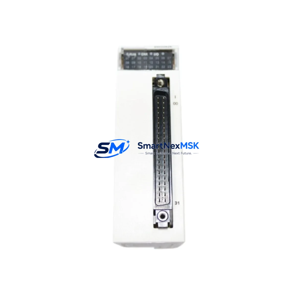
The Schneider Electric 140DDI36300, paired with the 990NAD23000 Modbus Plus network adapter cable, is a proven retrofit solution for aging Modicon Quantum automation platforms. Designed as a 32-channel, 24VDC discrete input module, the 140DDI36300 slots directly into the Quantum backplane — including the 140XBP01600 16-slot rack and the 140XBP00600 6-slot rack — without requiring mechanical modification or rack replacement. For facilities running legacy Quantum systems built around the 140CPU65150 or 140CPU67160 processors, this module represents the lowest-risk path to restoring or expanding discrete input capacity while preserving existing program logic and HMI configurations.
When planning a retrofit around the 140DDI36300, engineers must verify several critical compatibility parameters before installation. First, confirm available backplane power budget: the Quantum power supply — typically a 140CPS11420 or 140CPS21400 — must have sufficient residual capacity to support the additional 32-channel input load. Second, review terminal block wiring against the original I/O map; the 140DDI36300 uses a 40-pin Telefast-compatible connector, and field wiring from the legacy module should be re-terminated carefully to preserve channel-to-address mapping. Third, validate the module slot address assignment in Unity Pro or Concept programming software to ensure the replacement module occupies the same logical address as the removed unit, preventing any mismatch in the PLC scan cycle.
The 990NAD23000 cable is essential when the Quantum system communicates over Modbus Plus — a peer-to-peer token-passing network widely used in legacy Quantum installations. This cable connects the CPU or network module port to the Modbus Plus trunk, maintaining communication continuity with upstream SCADA systems, operator panels such as the XBTGT5330 Magelis HMI, and peer PLCs on the same network segment. Before disconnecting the existing cable, document the Modbus Plus node address and verify that no address conflicts exist on the network after the module swap.
For sites migrating from older Quantum I/O modules such as the discontinued 140DDI35300 or 140DDI84100, the 140DDI36300 provides a functionally equivalent replacement with improved input filtering and diagnostic LED indicators per channel. The transition requires no changes to the Unity Pro or Concept application program provided the slot address and I/O map remain consistent. If the site is also upgrading the communication infrastructure from Modbus Plus to Ethernet/IP, the 140NOE77101 Ethernet communication module can be installed in a parallel slot to support dual-protocol operation during the transition period, allowing a phased cutover without full system shutdown.
Downtime planning is critical for any Quantum retrofit. SMARTNEXMSK recommends pre-staging the 140DDI36300 and 990NAD23000 as a tested assembly before the maintenance window. Each unit shipped by SMARTNEXMSK undergoes functional power-on verification and is supplied with a 12-month warranty covering manufacturing defects and operational failures. Having a pre-tested spare on the shelf — alongside a backup of the current Unity Pro or Concept application — allows the field team to complete the module swap, re-terminate field wiring, restore the program, and verify I/O status within a single planned outage window, typically under four hours for a single-slot replacement.
Upgrade Compatibility Table
| Parameter | 140DDI36300 Details |
|---|---|
| Module Type | 32-Channel 24VDC Discrete Input |
| Compatible Racks | 140XBP01600 (16-slot), 140XBP00600 (6-slot), 140XBP00400 (4-slot) |
| Compatible CPUs | 140CPU65150, 140CPU67160, 140CPU43412A |
| Communication Protocol | Modbus Plus (via 990NAD23000), Modbus RTU, Ethernet/IP (with 140NOE77101) |
| Connector Type | 40-pin Telefast / HE10 compatible |
| Input Voltage | 24VDC (IEC Type 1) |
| Replaces | 140DDI35300, 140DDI84100 (legacy discontinued models) |
| Programming Software | Unity Pro, Concept 2.6+ |
| Installation | Hot-swap capable (with CPU in Stop mode); no rack modification required |
| Debugging Tools | Unity Pro I/O diagnostics, per-channel LED status indicators |
| Warranty | 12 Months — covers manufacturing defects and operational failures |
| Origin | France (Schneider Electric OEM) |
Retrofit Planning for Existing Automation Systems
A successful 140DDI36300 retrofit begins with a thorough audit of the existing Quantum control cabinet. Start by documenting the current rack layout — recording which modules occupy each slot in the 140XBP01600 backplane, including any 140ACI04000 analog input modules, 140DDO35300 discrete output modules, and 140EHC10500 high-speed counter modules sharing the same rack. This audit prevents accidental address conflicts when the new input module is inserted.
Next, review the power distribution within the control cabinet. The 140CPS11420 power supply feeding the Quantum rack must be verified against its published load curve; adding a 32-channel input module increases the 5VDC backplane current draw, and the power budget must accommodate this without triggering the supply’s overload protection. If the existing supply is already near capacity, a second 140CPS21400 supply may need to be added to the rack before the 140DDI36300 is installed.
Field wiring re-termination is the most time-sensitive step. The 40-pin HE10 connector on the 140DDI36300 is compatible with standard Telefast pre-wired cable assemblies, which can significantly reduce re-termination time compared to individual wire-by-wire connections. If the legacy module used a different connector format, a Telefast adapter sub-base may be required. Verify channel polarity and common terminal assignments against the original wiring diagram before energizing the field circuits.
For sites that also need to extend I/O capacity beyond what the local rack supports, the 140CRA93200 remote I/O adapter module allows additional Quantum I/O drops to be connected over the Modbus Plus network, enabling distributed I/O expansion without running additional backplane cables. This is particularly useful in large control cabinets where physical rack space is limited.
Finally, before returning the system to automatic operation, perform a full I/O force test using Unity Pro’s animation table to verify that each of the 32 input channels responds correctly to field signals. Cross-reference the results against the original I/O acceptance test records to confirm that the retrofit has restored full system functionality.
Downtime Control During System Migration
Minimizing unplanned downtime during a Quantum module replacement requires preparation at three levels: documentation, pre-staging, and execution discipline. Before the maintenance window opens, the engineering team should export a full backup of the Unity Pro or Concept application from the 140CPU65150 or 140CPU67160 processor and store it on a local programming terminal as well as a secure network share. This backup preserves all ladder logic, function block diagrams, data tables, and HMI variable bindings — ensuring that even if the CPU loses its program during the swap, recovery takes minutes rather than hours.
Pre-stage the 140DDI36300 and 990NAD23000 as a complete, tested assembly. SMARTNEXMSK performs power-on functional verification on every unit before shipment, but the site team should also confirm module LED behavior on a bench rack — such as a spare 140XBP00400 4-slot rack with a test power supply — before bringing the module to the production floor. This eliminates the risk of discovering a DOA module during the live maintenance window.
During the actual swap, place the Quantum CPU in Stop mode before removing the existing input module. This prevents the processor from generating I/O fault alarms that could propagate to the SCADA system or trigger interlock logic. After inserting the 140DDI36300, restore the program from backup, set the CPU back to Run mode, and verify I/O status via the Unity Pro diagnostics screen before releasing the system to operations. For sites with a XBTGT5330 Magelis HMI connected over Modbus Plus, confirm that all HMI variable bindings are reading correctly before signing off on the retrofit.
With proper preparation, a single-slot 140DDI36300 replacement can be completed within a two-to-four hour planned maintenance window, preserving production continuity and avoiding the extended downtime associated with unplanned failures of aging discrete input modules.
Retrofit Support FAQ
Q: Is the 140DDI36300 a direct drop-in replacement for the 140DDI35300?
A: Yes. The 140DDI36300 is the current production replacement for the discontinued 140DDI35300. It occupies the same backplane slot, uses the same 40-pin HE10 connector, and requires no changes to the Unity Pro or Concept application program provided the slot address remains the same. Channel count and input voltage ratings are identical.
Q: Does the 990NAD23000 cable need to be replaced if the existing Modbus Plus cable is still functional?
A: Not necessarily. If the existing 990NAD23000 cable is undamaged and the Modbus Plus network is operating correctly, it can be reused. However, SMARTNEXMSK recommends replacing the cable as a precaution during any planned retrofit, as aged cables are a common source of intermittent Modbus Plus communication faults that are difficult to diagnose under production conditions.
Q: What commissioning steps are required after installing the 140DDI36300?
A: After physical installation and program restore, perform the following: (1) verify module LED status — RUN green, I/O active per channel; (2) use Unity Pro animation table to force-test all 32 input channels against field signals; (3) confirm Modbus Plus node address and network token passing via the Modbus Plus statistics screen; (4) check HMI variable bindings on the Magelis panel; (5) document results in the site commissioning record before returning to automatic operation.
Q: What does the 12-month warranty cover?
A: The 12-month warranty provided by SMARTNEXMSK covers manufacturing defects and operational failures under normal industrial operating conditions. It includes free replacement or repair of the defective unit. The warranty does not cover damage caused by incorrect installation, overvoltage, reverse polarity, or physical impact. All units are functionally tested before shipment, and a test report is available upon request.
© 2026 SMARTNEXMSK. All rights reserved.
Original Source: https://smartnexmsk.com
Contact: sales@smartnexmsk.com | +86 18259474341