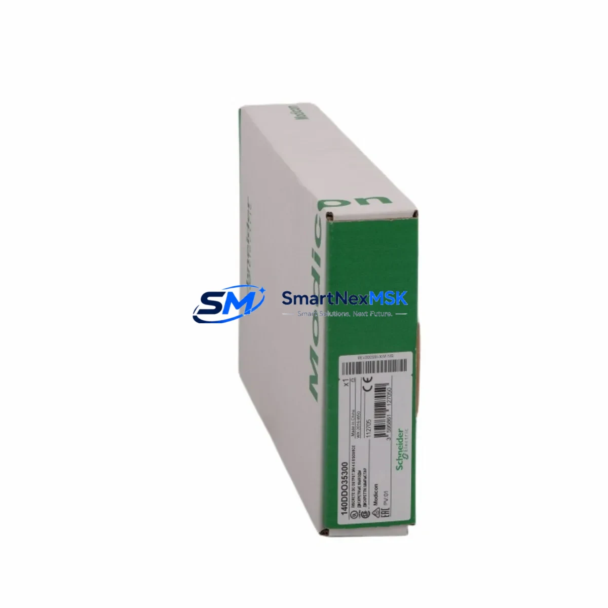
Schneider 140DDO35300 Retrofit-Ready Digital Output Module for Modicon Quantum Control Systems
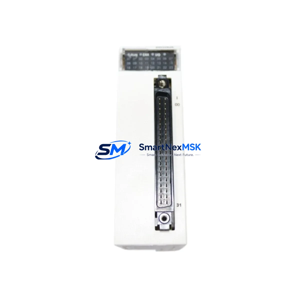
The Schneider Electric 140DDO35300 is a 32-channel, 24 VDC source-type digital output module engineered for the Modicon Quantum automation platform. As legacy Quantum systems approach end-of-life and spare-part availability tightens, the 140DDO35300 has become one of the most sought-after drop-in replacements for aging output modules across process plants, utilities, and discrete manufacturing lines. Whether you are executing a planned control-cabinet upgrade, recovering from an unplanned module failure, or migrating I/O racks to a modernized architecture, this module delivers the electrical compatibility, software transparency, and physical form factor required to restore or extend system operation with minimal disruption.
Each unit ships fully tested against Schneider Electric factory specifications, covered by a 12-month warranty, and is available from in-stock inventory for same-week dispatch to global destinations. Our technical team supports pre-shipment configuration verification and post-installation commissioning guidance at no additional charge.
Upgrade Compatibility Table
| Parameter | 140DDO35300 Specification | Retrofit / Upgrade Notes |
|---|---|---|
| Output Channels | 32 × 24 VDC source-type | Direct channel-for-channel replacement of earlier 140DDO3530x variants |
| Backplane Interface | Modicon Quantum local/remote I/O bus | Compatible with 140XBP01600, 140XBP00600, and 140XBP00400 backplanes |
| Module Slot | Any standard Quantum I/O slot | No slot-type restriction; address set via DIP switch or Unity Pro configuration |
| Terminal Wiring | 40-pin removable terminal block (field-side) | Existing field wiring re-connects without re-termination if original block is retained |
| Communication Compatibility | Modbus Plus, Ethernet/IP via CRP (140CRP93200 / 140NOE77101) | No protocol migration required; module is transparent to network layer |
| Programming Environment | Unity Pro XL / Unity Pro M (v2.0+) | Existing ladder, FBD, and SFC logic runs without modification after hot-swap |
| Power Consumption | ≤ 3.5 W backplane; field load per channel ≤ 0.5 A | Verify 140CPS11420 or 140CPS21400 power supply headroom before adding modules |
| Installation Requirement | DIN-rail or panel-mount rack; standard Quantum form factor | No mechanical modification to existing cabinet required |
| Replacement Recommendation | Direct swap for 140DDO35300, 140DDO35301 | Confirm firmware revision of 140CPU65160 or 140CPU67160 CPU for full compatibility |
| Commissioning Focus | Module address, output forcing, diagnostics enable | Use Unity Pro online mode to verify I/O map and force-test each channel before handover |
| Warranty | 12 Months | Covers manufacturing defects; includes pre-shipment functional test report |
Retrofit Planning for Existing Automation Systems
A successful retrofit of the 140DDO35300 into an operating Modicon Quantum system begins well before the module arrives on site. The first step is a thorough audit of the existing rack assembly. Identify the backplane model — typically a 140XBP01600 (16-slot) or 140XBP00600 (6-slot) — and confirm that the target slot is mechanically clear and that the backplane bus connector shows no corrosion or pin damage. Document the current slot address assignment in Unity Pro so the replacement module inherits the identical I/O map without requiring a program download.
Power budget verification is critical. The 140CPS11420 or 140CPS21400 power supply feeding the rack must have sufficient margin to support the 140DDO35300’s backplane draw alongside all co-resident modules — including analog input cards, communication modules such as the 140NOE77101 Ethernet adapter, and any 140ACI04000 analog input modules sharing the same rack. A rack that is already running near its power ceiling may require a second power supply or load redistribution before the new output module is installed.
Terminal wiring is one of the most time-sensitive elements of any output module replacement. The 140DDO35300 uses a 40-pin removable terminal block on the field side. If the original terminal block from the failed module is intact, it can be transferred directly to the replacement unit, preserving all field wiring connections and eliminating re-termination risk. Where the original block is damaged, each of the 32 output channels must be re-landed and continuity-verified against the as-built wiring diagram before energization.
For systems that also involve communication infrastructure upgrades — for example, migrating from a legacy Modbus Plus network to Ethernet/IP — the 140DDO35300 itself requires no reconfiguration, as it is transparent to the network layer. The communication change is handled entirely at the 140CRP93200 remote I/O head or the 140NOE77101 network option module level. This separation of concerns allows I/O module replacement and protocol migration to be sequenced independently, reducing the scope of any single maintenance window.
Where the retrofit scope extends beyond a single module — for instance, when an entire I/O rack is being replaced or when the project involves adding 140DDI35300 digital input modules alongside new output capacity — it is advisable to pre-stage the complete rack assembly, including the backplane, power supply, CPU or remote I/O head, and all I/O modules, in a workshop environment. Pre-staging allows full functional testing of the assembled rack against a copy of the production program before the unit is transported to the field, compressing on-site commissioning time to a single shift.
HMI screens connected via Vijeo Designer or third-party SCADA systems referencing Quantum I/O addresses will continue to function without modification, provided the replacement module occupies the same slot and address as its predecessor. If the slot address changes for any reason, all HMI tag bindings and SCADA point mappings referencing that address range must be updated and re-tested before the system is returned to automatic control.
Downtime Control During System Migration
Minimizing unplanned downtime during a Modicon Quantum output module replacement requires a structured approach to change management, spare-part pre-positioning, and on-site execution discipline. The 140DDO35300 supports hot-swap replacement in most Quantum rack configurations, meaning the module can be removed and reinserted while the rack remains powered — provided the CPU is placed in Stop mode and all associated output channels are confirmed de-energized at the field level before the swap begins. This procedure eliminates the need for a full rack power-down and preserves the state of all other modules in the rack.
Before initiating the swap, export and archive the current Unity Pro project file, including all variable tables, I/O configuration, and communication settings. This backup ensures that if the replacement module requires a fresh configuration download — for example, if the module’s internal parameters have been reset — the correct program version is immediately available without searching through version-control archives under time pressure.
After physical installation, use Unity Pro’s online diagnostic view to confirm that the 140DDO35300 is recognized by the CPU, that its I/O map matches the archived configuration, and that no channel-level faults are reported. Force each output channel individually through the Unity Pro forcing table and verify the corresponding field device response before releasing the system to automatic control. This channel-by-channel verification, while methodical, is the single most effective step for catching wiring errors or address mismatches before they cause a process upset.
For sites where even a brief Stop-mode interruption is unacceptable, coordinate the replacement with the process control team to identify a natural production break — a shift changeover, a scheduled cleaning cycle, or a planned product changeover — during which the output module swap can be executed within the available window. Pre-positioning a tested, configured spare 140DDO35300 in the control room ensures that the physical swap can be completed in under ten minutes, with the remainder of the window available for verification and sign-off.
Retrofit Support FAQ
Q1: Is the 140DDO35300 a direct drop-in replacement for the 140DDO35301?
Yes. The 140DDO35300 and 140DDO35301 share the same electrical specification, backplane pinout, and terminal block footprint. The revision suffix reflects a minor manufacturing change that does not affect field interchangeability. No program modification or address reassignment is required when substituting one revision for the other.
Q2: What commissioning steps are required after installing the replacement module?
After physical installation, place the CPU in Stop mode and perform a Unity Pro online connection. Verify that the module appears in the I/O configuration tree with no fault indicators. Confirm the slot address matches the original assignment, then use the forcing table to test each of the 32 output channels against the field wiring. Once all channels are verified, clear any forced values, return the CPU to Run mode, and monitor the first production cycle for unexpected output behavior.
Q3: Can the existing field wiring terminal block be reused?
In most cases, yes. The 40-pin removable terminal block is a field-replaceable component that transfers directly from the old module to the new one. Reusing the original block eliminates re-termination work and reduces the risk of wiring errors. Inspect the block for damaged pins, loose screws, or heat discoloration before transfer; replace the block if any defects are found.
Q4: What does the 12-month warranty cover, and is a test report included?
The 12-month warranty covers all manufacturing defects and functional failures under normal operating conditions. Each 140DDO35300 unit undergoes a pre-shipment functional test that verifies backplane communication, channel-level output switching, and diagnostic reporting. A test report is available upon request and can be included with the shipment documentation for quality-assurance records.
© 2026 SMARTNEXMSK. All rights reserved.
Original Source: https://smartnexmsk.com
Contact: sales@smartnexmsk.com | +86 18259474341