Schneider 140DDO35310 Retrofit-Ready Output Module for Quantum Control Systems
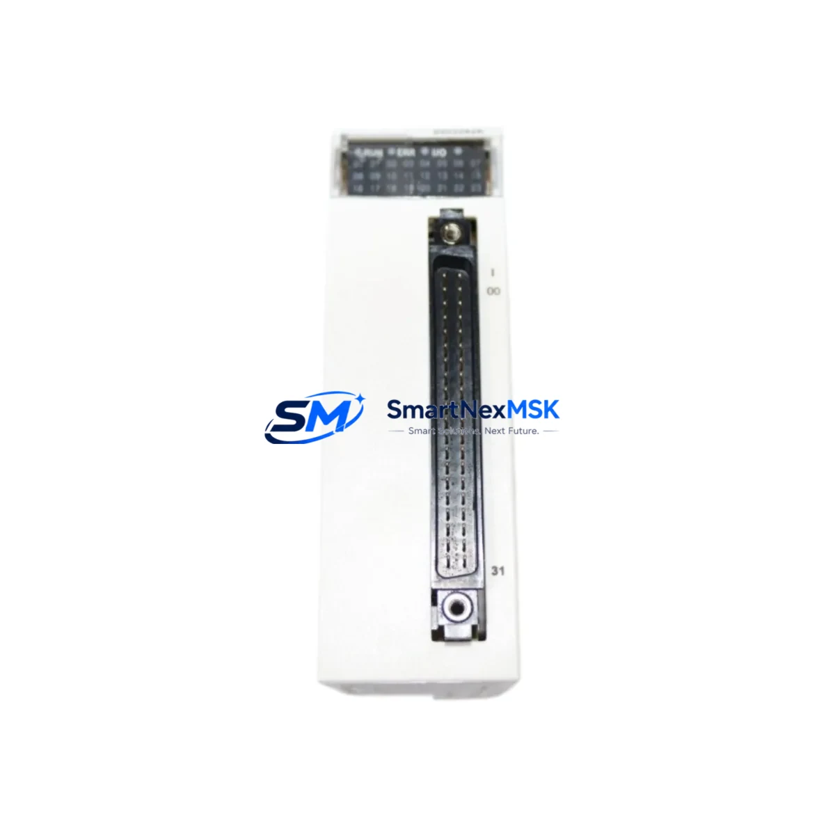
The Schneider Electric 140DDO35310 is a 32-channel, 24 VDC transistor discrete output module engineered for the Modicon Quantum PLC platform. Designed for direct backplane installation in Quantum I/O racks, this module delivers reliable digital output control across demanding industrial environments including automotive assembly, water treatment, oil & gas processing, and discrete manufacturing. Whether you are replacing a failed module on an aging production line, upgrading a legacy control cabinet, or executing a planned system modernization, the 140DDO35310 provides a verified, drop-in retrofit path with no firmware changes required on most Quantum CPU configurations.
For engineers managing aging Modicon Quantum installations, sourcing a proven replacement for the 140DDO35310 is often the fastest route to restoring production continuity. Unlike full PLC migrations that require re-engineering the control architecture, a like-for-like module swap preserves the existing Unity Pro or Concept application program, retains all I/O addressing, and eliminates the need to re-commission field wiring. This makes the 140DDO35310 the preferred choice for maintenance teams operating under tight downtime windows.
Upgrade Compatibility Table
| Parameter | 140DDO35310 Specification | Retrofit / Upgrade Notes |
|---|---|---|
| Output Channels | 32 channels, transistor (sourcing) | Direct replacement for 140DDO35300 (16-ch) requires I/O map update |
| Output Voltage | 24 VDC nominal | Verify field device supply voltage before wiring |
| Output Current | 0.5 A per channel, 8 A per module | Check aggregate load; derate in high-ambient enclosures |
| Backplane Interface | Modicon Quantum I/O bus | Compatible with 140XBP00600, 140XBP01600 racks |
| Module Slot Address | Configurable via Unity Pro / Concept | Must match original slot address in application program |
| Communication Protocol | Quantum local I/O bus (not standalone Modbus/TCP) | Remote I/O via 140CRA93100 RIO head adapter supported |
| Installation Format | Single-slot Quantum module | No additional mounting hardware required |
| Programming Environment | Unity Pro XL / Concept 2.6+ | No program modification needed for like-for-like swap |
| Diagnostics | LED status per channel group | Verify diagnostic mapping in HMI (Magelis / SCADA) after swap |
| Warranty | 12-Month Warranty — covers manufacturing defects; includes pre-shipment functional test | |
Retrofit Planning for Existing Automation Systems
A successful 140DDO35310 retrofit begins well before the module arrives on site. The first step is a thorough audit of the existing Quantum rack configuration. Identify the 140XBP00600 or 140XBP01600 backplane currently in service, confirm available slot positions, and document the power budget supplied by the 140CPS11420 or 140CPS21400 power supply module. The 140DDO35310 draws current from the backplane 5 VDC bus; exceeding the power supply’s rated output across all installed modules is a common oversight that causes intermittent faults after replacement.
Terminal wiring is the next critical checkpoint. The 140DDO35310 uses a 40-pin removable terminal block. Before disconnecting the existing module, photograph or document all field wiring assignments. If the outgoing module is a 140DDO35300 (16-channel variant), the wiring layout differs — channels 17–32 will require new field connections and corresponding updates to the Unity Pro I/O configuration. For systems using a 140CRA93100 remote I/O head adapter to extend the Quantum rack over a coaxial RIO network, confirm that the RIO drop address and module slot number are correctly reflected in the CPU’s configuration table before going live.
Communication integrity is equally important in multi-rack Quantum architectures. Systems that rely on a 140NOE77101 Ethernet communication module for Modbus/TCP supervisory access, or a 140NOM21100 Modbus Plus network module for peer-to-peer data exchange, should have their network health verified after the module swap. A brief network interruption during hot-swap is normal; confirm that all peer stations re-establish communication within the expected timeout window defined in the application program.
HMI screens built on Magelis iPC or third-party SCADA platforms that display individual output channel states should be reviewed after replacement. If the original module had custom diagnostic tags mapped to specific memory addresses in the Quantum CPU, verify that those addresses remain valid after the swap. In most like-for-like replacements, no HMI modification is required, but it is best practice to cycle through all affected display pages during commissioning to confirm correct status indication.
For sites running a 140CPU65160 or 140CPU67160 hot-standby CPU pair, the module replacement procedure must account for the standby switchover sequence. Perform the swap on the primary rack while the standby CPU holds control, then synchronize and verify before returning the primary to active status. This approach eliminates unplanned process interruptions and is consistent with Schneider Electric’s recommended hot-standby maintenance procedure.
Downtime Control During System Migration
Minimizing unplanned downtime during a 140DDO35310 replacement requires a structured pre-outage checklist. Before removing power from the affected rack, upload and save the current application program from the Quantum CPU using Unity Pro or Concept. Store the backup on a dedicated engineering laptop and a secondary USB drive — never rely on a single copy during live maintenance. If the system supports online program modification, verify that the replacement module’s firmware revision is compatible with the CPU firmware currently in service; mismatched firmware can prevent the module from being recognized at startup.
During the physical swap, observe standard ESD precautions. The 140DDO35310’s backplane connector is sensitive to electrostatic discharge, and damage may not be immediately visible but can cause latent output failures. Once the new module is seated and the terminal block re-connected, apply power and observe the module’s RUN and I/O status LEDs. A solid green RUN LED with no flashing fault indicators confirms successful initialization. Force individual output channels from the Unity Pro online monitor to verify field device response before releasing the system to production.
For planned migrations from older Quantum configurations to a newer Modicon M580 architecture, the 140DDO35310 can serve as an interim solution — maintaining the existing Quantum rack in service while the M580 infrastructure is staged and tested in parallel. This phased approach protects original program logic, preserves field wiring, and allows the engineering team to validate the new platform without committing to a hard cutover under production pressure.
Retrofit Support FAQ
Q1: Is the 140DDO35310 a direct drop-in replacement for the 140DDO35300?
The 140DDO35310 (32-channel) and 140DDO35300 (16-channel) share the same physical form factor and backplane connector, but differ in channel count and terminal block wiring. A direct swap requires updating the I/O configuration in Unity Pro or Concept to reflect the additional 16 channels, and field wiring for channels 17–32 must be connected. For a true like-for-like replacement, source another 140DDO35310.
Q2: What pre-shipment testing is performed on the 140DDO35310?
Each unit undergoes functional output verification across all 32 channels, backplane connector inspection, and LED diagnostic confirmation prior to shipment. A test report is available upon request. All units are covered by a 12-month warranty against manufacturing defects from the date of delivery.
Q3: Can the 140DDO35310 be used in a Quantum hot-standby system?
Yes. The module is fully compatible with Quantum hot-standby CPU configurations including the 140CPU65160 and 140CPU67160. Follow Schneider Electric’s hot-standby maintenance procedure: perform the swap on the primary rack while the standby holds control, then re-synchronize before returning the primary to active status.
Q4: How do I verify wiring compatibility before installation?
Compare the existing terminal block wiring diagram against the 140DDO35310 installation guide (document reference 840USE10000). Confirm output channel groupings, common terminal assignments, and field device voltage ratings. If the original module’s terminal block is removable and undamaged, it can be transferred directly to the replacement module, preserving all field wiring connections and reducing installation time significantly.
© 2026 SMARTNEXMSK. All rights reserved.
Original Source: https://smartnexmsk.com
Contact: sales@smartnexmsk.com | +86 18259474341