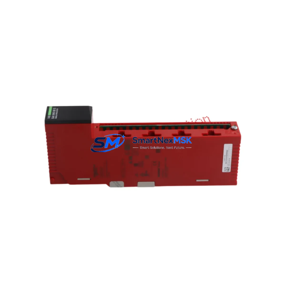
Schneider 140SAI94000S Retrofit-Ready Analogue Safety Input for Quantum Control Systems
The Schneider Electric 140SAI94000S is a high-integrity analogue safety input module engineered for the Modicon Quantum PLC platform — one of the most widely deployed process-control architectures in petrochemical, power generation, water treatment, and heavy manufacturing facilities worldwide. As legacy Quantum installations approach end-of-life milestones, the 140SAI94000S has become a critical retrofit component for engineers tasked with extending system lifespan, replacing discontinued safety I/O, and maintaining SIL-rated loop integrity without a full control-system overhaul.
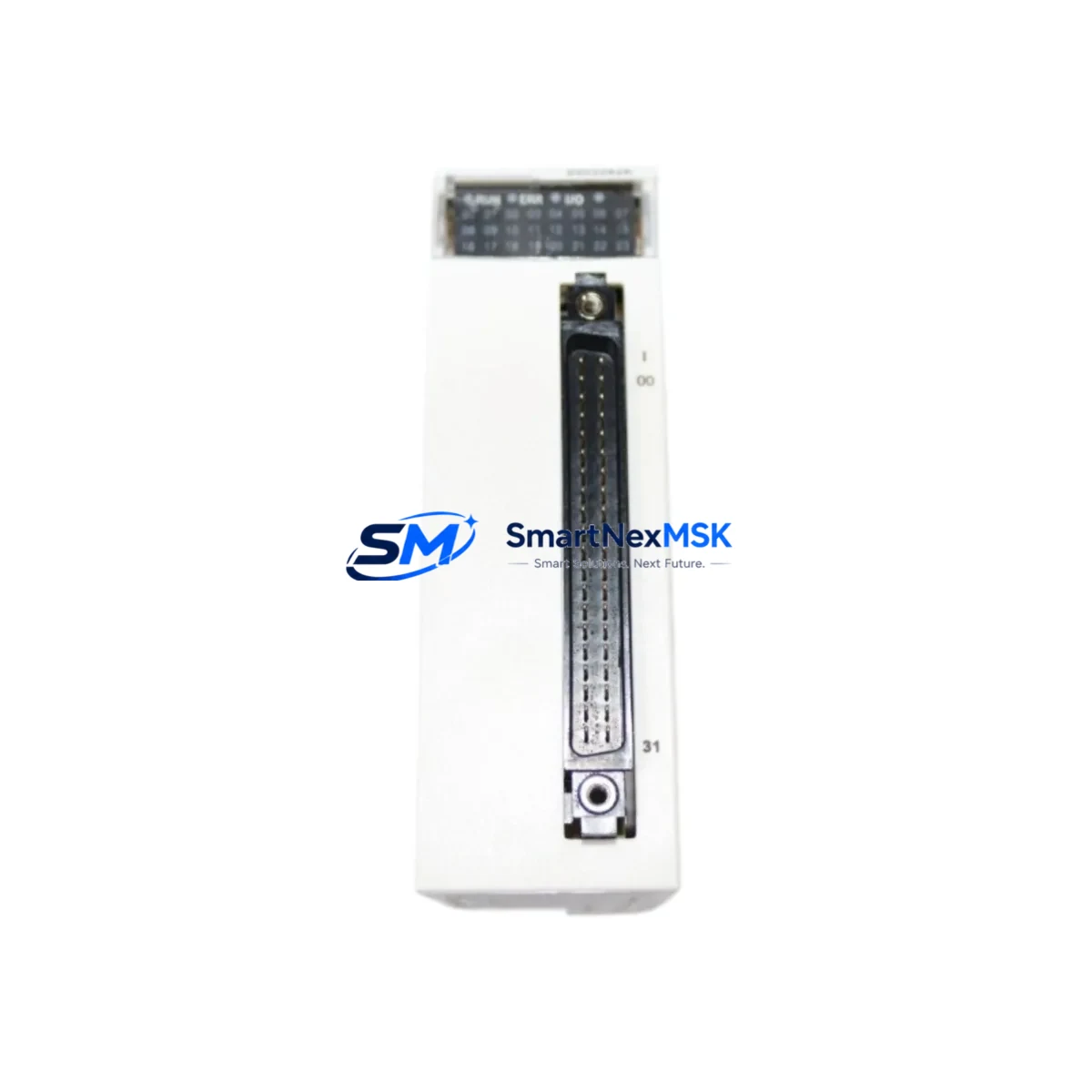
This module accepts analogue field signals from safety-rated transmitters and sensors, conditions them through isolated input channels, and delivers validated process values to the Quantum CPU — typically a 140CPU67160 or 140CPU65160 — via the local backplane bus. Its direct compatibility with the Quantum 140-series rack architecture means no adapter plates, no firmware bridging, and no rewiring of existing marshalling panels when used as a like-for-like replacement for a failed or obsolete safety input card.
For sites running mixed Quantum configurations — combining standard I/O racks with dedicated safety racks — the 140SAI94000S slots into the same 140XBP01600 or 140XBP00600 backplane positions as its predecessors. Engineers should verify slot addressing in Unity Pro or Concept software before hot-insertion, particularly where the safety rack communicates with a 140NOM21100 or 140NOE77111 Ethernet communications module that feeds SCADA or DCS historian layers.
Upgrade Compatibility Table
| Parameter | Detail |
|---|---|
| Module SKU | 140SAI94000S |
| Platform | Modicon Quantum (140-series) |
| Module Type | Analogue Safety Input Module |
| Signal Type | Analogue (4–20 mA / 0–10 V field inputs, isolated) |
| Backplane Compatibility | 140XBP01600, 140XBP00600 (Quantum 16-slot & 6-slot racks) |
| CPU Compatibility | 140CPU67160, 140CPU65160, 140CPU43412A and compatible Quantum CPUs |
| Programming Environment | Unity Pro (v4.0+), Concept (legacy) |
| Communication Interface | Quantum local backplane bus; compatible with 140NOE77111 Ethernet module |
| Installation Requirement | DIN-rail rack mount; no adapter required for direct slot replacement |
| Replacement Recommendation | Direct drop-in for failed or EOL 140SAI94000S units; verify I/O map and module address in Unity Pro before restart |
| Commissioning Focus | Channel calibration, SIL loop validation, safety function proof-test, SCADA tag re-binding |
| Warranty | 12 Months — covers manufacturing defects, functional failure under normal operating conditions |
| Origin | France (Schneider Electric) |
| Shipping | Global express; ESD-safe packaging; pre-shipment functional test |
Retrofit Planning for Existing Automation Systems
A successful 140SAI94000S retrofit begins well before the module arrives on-site. The first step is a thorough audit of the existing Quantum rack layout. In most installations, the safety input module occupies a dedicated slot within a segregated safety rack, physically separated from standard process I/O to maintain SIL integrity. Confirm the rack model — whether a 140XBP01600 16-slot or a 140XBP00600 6-slot backplane — and document the slot number assigned to the outgoing module. This slot address must be preserved in the Unity Pro hardware configuration to avoid I/O map conflicts that would force a full program download and extended downtime.
Power budget verification is equally critical. The Quantum power supply — commonly a 140CPS11420 or 140CPS21400 — must have sufficient headroom to support the 140SAI94000S alongside all co-resident modules. Pull the rack’s power consumption worksheet and confirm that the replacement module’s current draw does not push the supply beyond 80% of rated capacity. If the existing supply is already marginal, a parallel power supply or rack redistribution may be required before the retrofit can proceed safely.
Terminal wiring is the next checkpoint. The 140SAI94000S uses a standard Quantum front-connector wiring scheme. Field cables from safety transmitters — pressure, temperature, flow, or level instruments — terminate at the module’s removable screw terminal block. Verify that existing cable labels match the channel assignments documented in the original loop drawings. Any discrepancy between the physical wiring and the Unity Pro I/O configuration will produce channel faults that the safety CPU will interpret as a safety function failure, potentially triggering a controlled shutdown.
For sites where the Quantum system communicates upstream via a 140NOE77111 Ethernet module or a 140NOM21100 Modbus Plus network module, confirm that SCADA tag addresses and historian mappings remain intact after the module swap. In Unity Pro, re-download only the modified rack section if the CPU supports partial downloads — this minimises the risk of inadvertently altering unrelated program sections. Where the HMI layer — often a Magelis XBTGT or third-party SCADA — displays safety loop status, verify that all analogue input tags resolve correctly after the module is powered and initialised.
Finally, conduct a full proof-test of each safety function associated with the replaced module. Inject a known reference signal at each channel input, confirm that the CPU reads the expected engineering-unit value within tolerance, and verify that the safety function trips at the configured setpoint. Log all test results in the site’s safety management system before returning the loop to automatic control.
Downtime Control During System Migration
Minimising unplanned downtime during a 140SAI94000S replacement requires a structured pre-outage preparation protocol. Before the maintenance window opens, export the current Unity Pro project and store a timestamped backup on an isolated engineering workstation. If the site uses a 140CPU67160 with hot-standby capability via a 140CHS21000 hot-standby module, coordinate the swap to occur while the standby CPU holds control — this can reduce the control interruption to the duration of a single switchover event rather than a full rack power cycle.
For non-redundant Quantum configurations, pre-stage the replacement 140SAI94000S module in a bench test environment if possible. Connect a loop calibrator to each input channel and verify that the module responds correctly before it enters the production rack. This pre-commissioning step catches infant-mortality failures and eliminates the risk of installing a defective unit during a live maintenance window.
During the physical swap, de-energise only the affected rack section where safety interlocks permit. Remove the front connector wiring harness as a single assembly — do not disconnect individual field cables — to preserve terminal assignments. Seat the replacement module firmly into the backplane, reattach the front connector, and restore rack power. Monitor the Unity Pro diagnostics screen for channel initialisation status before releasing the safety loops to automatic control. Document the exact time of module replacement, the pre- and post-swap proof-test results, and the technician sign-off in the site’s maintenance management system.
Retrofit Support FAQ
Q1: Is the 140SAI94000S a direct drop-in replacement for an existing failed unit in a Modicon Quantum rack?
Yes. The 140SAI94000S is designed for direct slot-for-slot replacement within any compatible Quantum 140-series rack. No hardware adapters are required. You must verify that the slot address in your Unity Pro hardware configuration matches the physical slot position, and perform a channel proof-test after installation to confirm SIL loop integrity before returning to automatic control.
Q2: What wiring changes are needed when replacing an older 140SAI94000S with a new unit?
In most cases, no wiring changes are required. The replacement module uses the same removable front-connector terminal block as the original. Remove the connector as a single assembly, seat the new module, and reattach the connector. Verify channel assignments against your loop drawings before powering up. If field cables have been re-terminated or re-labelled since the original installation, reconcile the physical wiring against the Unity Pro I/O map before commissioning.
Q3: How do I confirm communication compatibility with my existing Quantum CPU and network modules?
The 140SAI94000S communicates via the Quantum local backplane bus and is compatible with all standard Quantum CPUs, including the 140CPU67160 and 140CPU65160 families. It does not require separate configuration for backplane communication. For upstream network modules such as the 140NOE77111 Ethernet module or 140NOM21100 Modbus Plus module, no additional configuration is needed — the module’s I/O data is mapped through the CPU’s I/O image table, which SCADA and DCS systems access via the network module as before.
Q4: What does the 12-month warranty cover, and what is the pre-shipment test process?
Every 140SAI94000S unit supplied by SMARTNEXMSK undergoes a pre-shipment functional test that verifies channel response, backplane communication, and power consumption within specification. The 12-month warranty covers manufacturing defects and functional failure under normal operating conditions from the date of delivery. Units are shipped in ESD-safe packaging with a test report. Warranty claims are processed directly — contact sales@smartnexmsk.com with your order reference and a description of the fault.
© 2026 SMARTNEXMSK. All rights reserved.
Original Source: https://smartnexmsk.com
Contact: sales@smartnexmsk.com | +86 18259474341