Schneider ATV930C16N4C Retrofit-Ready VFD for Altivar Process Control Systems
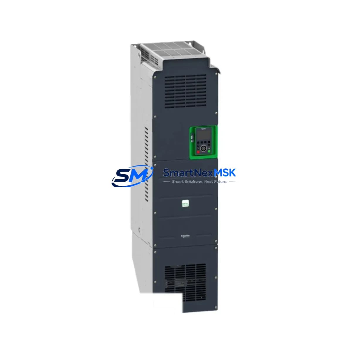
The Schneider Electric ATV930C16N4C is a 160kW (250HP) three-phase variable frequency drive from the Altivar Process ATV930 series, engineered for demanding industrial pump, fan, compressor, and mixer applications. As legacy Altivar 61 and Altivar 71 drives reach end-of-life and spare parts become increasingly scarce, the ATV930C16N4C has become the primary retrofit-ready replacement for modernizing existing control panels, motor control centers (MCCs), and distributed drive cabinets without requiring full system redesign.
SMARTNEXMSK maintains verified in-stock inventory of the ATV930C16N4C, fully tested prior to shipment, backed by a 12-month warranty, and available for fast global dispatch. Each unit is inspected against Schneider Electric factory specifications to ensure compatibility with existing wiring infrastructure, communication networks, and SCADA/DCS integration points.
Upgrade Compatibility Table
| Parameter | Legacy (ATV61 / ATV71) | ATV930C16N4C (Replacement) |
|---|---|---|
| Power Rating | 132–160kW (varies by model) | 160kW / 250HP |
| Supply Voltage | 380–480V AC 3-phase | 380–480V AC 3-phase (±10%) |
| Communication Protocols | Modbus RTU, CANopen, Profibus DP | Modbus TCP/IP, Profibus DP, EtherNet/IP, DeviceNet (via option card) |
| Control Terminal Wiring | Legacy 2-wire/3-wire terminal block | Compatible terminal layout; verify AI/AO/DI/DO mapping before commissioning |
| Mounting / Enclosure | Wall-mount or cabinet-mount | Cabinet-mount (IP21/IP54 options); verify cabinet depth ≥ 600mm |
| Fieldbus Option Cards | VW3A3xxx series cards | VW3A3xxx series cards (backward compatible) |
| HMI / Keypad | ATV61/71 graphic display terminal | Graphic display terminal (GDT) — parameter migration via SoMove software |
| Braking Resistor | External resistor required for high-inertia loads | External braking resistor compatible; verify VW3A7xxx resistor sizing |
| Commissioning Tool | PowerSuite / SoMove | SoMove (EcoStruxure Drive DTM) |
| Warranty | N/A (discontinued) | 12-Month Warranty (SMARTNEXMSK) |
Retrofit Planning for Existing Automation Systems
Replacing a legacy Altivar 61 or Altivar 71 drive with the ATV930C16N4C requires a structured pre-commissioning review to ensure electrical, mechanical, and software compatibility across the entire control loop. The following planning checklist covers the critical integration points engineers encounter during field retrofits.
Power Supply and Cabinet Sizing: Confirm that the existing MCC or drive cabinet can accommodate the ATV930C16N4C’s physical dimensions and heat dissipation requirements. The ATV930 series at 160kW generates significant thermal load; verify that cabinet ventilation, cooling fans, and clearance distances meet Schneider’s installation guidelines. If the existing cabinet houses a Schneider Altivar 61 C16N4 or Altivar 71 C16N4, the power bus connections and upstream circuit breaker (typically a Schneider NSX or Compact NS series MCCB rated at 400A or above) should be verified for compatibility with the ATV930’s input current profile.
Terminal Wiring and I/O Mapping: The ATV930C16N4C uses a revised terminal block layout compared to the ATV61/71 generation. Before disconnecting the legacy drive, photograph and document all existing AI (analog input), AO (analog output), DI (digital input), DO (digital output), and relay output wiring. Map each signal to the corresponding ATV930 terminal using Schneider’s migration guide. Pay particular attention to the speed reference signal (typically 4–20mA or 0–10V from a Modicon M340 or Premium PLC analog output module), the run/stop command wiring, and any fault relay outputs connected to the plant DCS or safety relay modules such as the Schneider Preventa XPSAF or XPSMF series.
Communication Protocol Migration: Many legacy Altivar 61 installations use Modbus RTU over RS-485 or CANopen for integration with Modicon Quantum, Modicon M340, or Modicon Premium PLCs. The ATV930C16N4C natively supports Modbus TCP/IP over Ethernet and can be fitted with a VW3A3608 Profibus DP option card or a VW3A3616 EtherNet/IP card for seamless integration into existing fieldbus architectures. If the plant network uses a Schneider ConneXium managed Ethernet switch or a Hirschmann RS20 series switch, verify that the ATV930’s IP address, subnet mask, and gateway settings are configured before energizing. Update the PLC program’s communication function blocks (e.g., READ_VAR / WRITE_VAR in Unity Pro or Control Expert) to reflect the new drive’s register map, which differs from the ATV61/71 Modbus register table.
Backplane, Rack, and Controller Integration: In distributed control architectures where the drive is supervised by a Modicon M580 or Modicon Quantum rack-based controller, confirm that the drive’s EtherNet/IP or Modbus TCP scanner configuration in the PLC rack is updated. If the existing system uses a Schneider TSXPSY2600M power supply module or a TSXRKY12EX rack extension, ensure that the updated drive I/O data map is reflected in the PLC’s I/O configuration table. For systems using a Vijeo Citect or Wonderware SCADA platform, update the tag database to reflect the new Modbus register addresses for speed reference, output frequency, motor current, fault codes, and drive status words.
HMI Screen Updates: If the plant uses a Schneider Magelis HMIGTO or HMISCU series HMI panel for local drive monitoring, the HMI project will require screen updates to reflect the ATV930’s parameter structure. Use Vijeo Designer or EcoStruxure Operator Terminal Expert to remap drive status tags, speed setpoint entry fields, and fault history displays. Verify that the HMI communication driver (Modbus TCP or Uni-Telway) is correctly configured for the ATV930’s IP address and port settings.
Pre-Energization Checklist: Before applying power to the ATV930C16N4C, verify insulation resistance of motor cables (minimum 1MΩ at 500VDC), confirm correct motor nameplate data entry (rated voltage, current, frequency, power factor, and speed), set the motor control type (vector control or V/f), configure acceleration and deceleration ramps to match process requirements, and verify that all safety interlocks — including emergency stop circuits wired through a Schneider TeSys D or TeSys K contactor — are functional before enabling the drive’s run command.
Downtime Control During System Migration
Minimizing production downtime during a drive retrofit is a primary concern for plant engineers and maintenance managers. A well-planned ATV930C16N4C installation can be completed within a single planned maintenance window, typically 4–8 hours for a 160kW drive replacement, provided that all pre-commissioning steps are completed in advance.
Pre-Shutdown Preparation: Before the maintenance window begins, use SoMove software to upload and save the complete parameter set from the existing Altivar 61 or Altivar 71 drive. Store this backup file securely — it serves as both a reference for the ATV930 parameter migration and a recovery baseline if the retrofit encounters unexpected issues. Simultaneously, prepare the ATV930C16N4C by pre-loading motor nameplate data, communication settings, and I/O configuration using SoMove in offline mode, so the drive is ready for final commissioning immediately after installation.
Protecting Existing Program Logic: The PLC program controlling the drive — whether running on a Modicon M340, Modicon M580, or a legacy Modicon Premium — should not require modification to its core logic if the Modbus register mapping is correctly updated. Use Control Expert or Unity Pro to create a backup of the PLC application before making any changes. If the drive is integrated via a Profibus DP network alongside other field devices such as Schneider ATV312 or ATV320 series drives on the same DP segment, verify that the ATV930’s GSD file is correctly imported into the Profibus master configuration and that the station address does not conflict with existing devices.
Maintaining Field Control Continuity: For critical process applications — such as cooling water pumps, boiler feed pumps, or compressor drives — consider implementing a temporary bypass contactor arrangement using a Schneider TeSys D LC1D series contactor to allow the motor to run at fixed speed (DOL) during the drive swap, maintaining process continuity. Once the ATV930C16N4C is installed and pre-commissioned, transfer control back to the drive during a brief process pause, verify speed reference tracking, and confirm fault-free operation before returning the system to automatic control from the DCS or PLC.
Retrofit Support FAQ
Q1: Is the ATV930C16N4C a direct drop-in replacement for the Altivar 61 ATV61C16N4 or Altivar 71 ATV71C16N4?
The ATV930C16N4C is the recommended upgrade path for both the ATV61C16N4 and ATV71C16N4. While the power rating and voltage class are equivalent, the terminal layout, parameter structure, and communication register map differ. A wiring adaptation and parameter migration using SoMove software is required. SMARTNEXMSK provides a pre-shipment configuration service upon request.
Q2: What communication options are available for integration with existing Modbus RTU or Profibus DP networks?
The ATV930C16N4C includes native Modbus TCP/IP via its onboard Ethernet port. For Profibus DP integration, the VW3A3608 option card must be installed. For CANopen networks, the VW3A3608 CANopen card is available. All option cards are backward compatible with the VW3A3xxx series used in ATV61/71 installations, simplifying the upgrade process.
Q3: How is the ATV930C16N4C tested before shipment?
Every unit supplied by SMARTNEXMSK undergoes a pre-shipment functional test including power-on verification, parameter initialization, communication port check, and output voltage balance measurement. Units are shipped with a test report. All units are covered by a 12-month warranty from the date of shipment, covering manufacturing defects and functional failures under normal operating conditions.
Q4: What is the lead time and can the unit be configured before dispatch?
In-stock units are available for same-day or next-business-day dispatch. Pre-configuration of motor parameters, IP address settings, and communication protocol selection is available upon request at no additional charge. Contact our technical team at sales@smartnexmsk.com or +86 18259474341 to discuss your specific retrofit requirements before placing an order.
© 2026 SMARTNEXMSK. All rights reserved.
Original Source: https://smartnexmsk.com
Contact: sales@smartnexmsk.com | +86 18259474341